112
EN
8 CASCADING SYSTEMS
8.1
Cascade characteristics
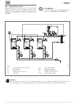
Each boiler connected in a cascade must be identified with a
specific address than can be set under the relevant parameter
(PAR 15), which determines how it behaves.
m
WARNINGS
For the cascade to function correctly, the external
sensor (SE) must be installed.
8.2
Characteristics of cascading boilers
Master boiler
The
master
boiler is the only boiler to which the TAs and the
room control units must be connected, as well as all of the
system components such as pumps, zone valves and external
sensors. It is the only one that communicates with the other
slave boilers in the cascade.
The heat requests are then sent to the master boiler and
managed according to an algorithm that controls the cascade
by turning the slave boilers on and off, and activating the pumps
and necessary valves, etc.
As well as controlling the specific boiler parameters, it also
controls the main cascade parameters.
Slave boiler no. 1
Slave
boiler no. 1 acts as the main slave boiler in the cascade.
The cascade delivery probe (SMC) MUST be connected to
connector CN4 on the electronic board. The temperature value
detected by the SMC probe is read cyclically and used by the
algorithm to manage the cascade in heating mode.
Slave boiler no.s ... (from no. 2 to no. 7)
All slave boilers contribute to producing the heat needed to
serve the connected systems, and each slave boiler receives an
on/off command from the master boiler only.
The function (user) buttons on all of the slave boilers are
disabled, with the exception of the RESET button which is used
ONLY in cases where the boiler locks out.. The installer buttons
remain enabled to ensure that the appliance is configured
correctly.
Producing domestic hot water
Domestic hot water is produced when a storage tank is installed
in the system which can be managed as a “direct system” or
assigned to any boiler in the cascade, whether master or slave.
The necessary parameters must clearly be set for managing
the probe, tank pump, anti-legionella and any priority or
simultaneous operation (PAR 2).
m
WARNINGS
When boilers are connected in a cascade, they
communicate ONLY with the master boiler, treating
the cascade as a single heat generator where:
Cascade output = Boiler output x no. of boilers installed
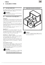
8.3
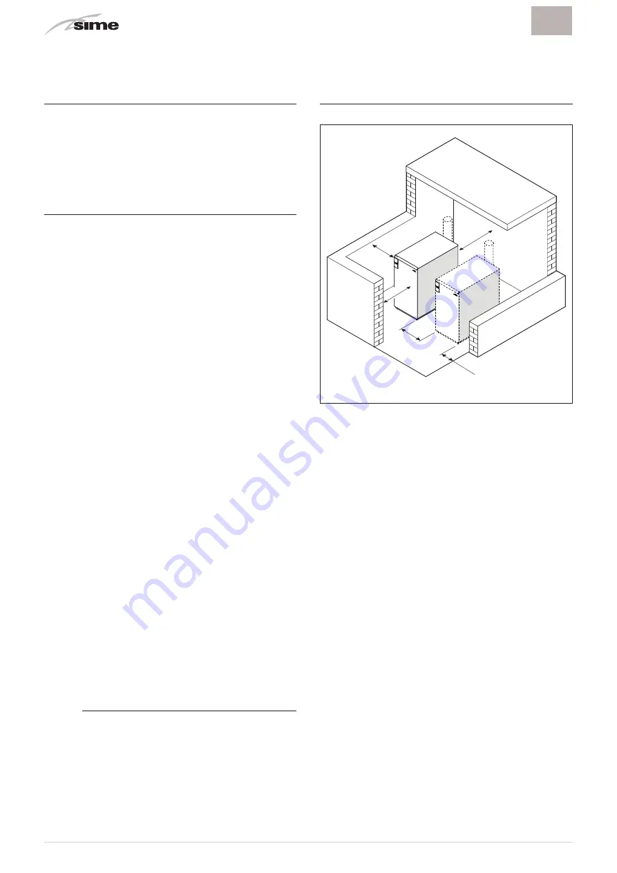
Approximate clearance measurements
≥
1,2 m
≥
1,2 m
≥
1,5 m
≥
1,2 m
≥
0,1 m
Fig. 44
m
CAUTION
Remember to consider the space needed in order to
access the safety/adjustment devices and to carry out
maintenance interventions.
Summary of Contents for ALU HE 116
Page 6: ...6 IT ...
Page 12: ...12 IT ...
Page 24: ...24 IT ...
Page 61: ...61 IT ...
Page 62: ...62 EN ...
Page 66: ...66 EN ...
Page 72: ...72 EN ...
Page 84: ...84 EN ...
Page 121: ...121 EN ...
Page 122: ...122 ...
Page 123: ...123 ...


