118
EN
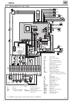
8.11 Wiring diagram for slave 1 boiler
5
4
N
L
2
1
BLUE
BLACK
BL
UE
BRO
WN
GREEN
RED
CD. 63228900
RED
ORANGE
GREEN
TPA
5V
GND
OUT
QU4
V
BROWN
BLA
CK
BRO
WN
BLUE
BLUE
CN1
CN2
CN3
CN4
CN5
CN6
CN7
CN9
CN18
CN10
CN11
CN14
CN13
CN12
32
36
49 50
58
1
1
2
3
4
5
6
7
8
9
10
4
5
N
L
6
7
10
69
64
69
72
68
72
11
17
20
A
21
24
26
31
C
18
35
F1
JP1
F2
BL
UE
BRO
WN
BROWN
TA1 230V
N
TRA
L
N
PE
Pc
p
N
PE
AC
S
N2
RISc
N3
SF
SF1
PC
PC1
GND
PWM
ER
MC
EA
AR
VZ
N
AUX
L
AUX
L
VZ
AR
BROWN
BLUE
11
12
13
14
15
16
17
SB/SA
BLACK
BLACK
BLA
CK
BLUE
BLUE
BLUE
BLUE
SM
KA
VD2
QU1
QU2
KA
VD1
KAPI
KAPI
QU3
KA
VD2
1 2 3 4 5 6 7 8 9 10 11 12 13 14 15 16 17 18
KAEV
KAEV
KAPI
KA
VD1
230 V - 50 Hz Pcp
L N
PM
VD
Connections to be made by the installer
PB
BROWN
EV
BLUE
VG
1
PM
RED
RED
TS
SPS
GREEN
BLUE
APS
Pm
P
P
C
C
NA
NC
NC
NA
P
OP
C
NC
NA
SMC
BROWN
GREEN
GREEN
SR
SF2
RS485
1
2
3
4
5
6
L
Line
N
Neutral
MCP
Primary circuit pump
PB
Storage tank pump
PM
Primary circuit
modulating pump(*)
VD
Diverter valve
PWM-GND
Modulating pump signal
(if present)
F1-F2
Fuses (4 AT)
TRA
Ignition transformer
V
Fan
SMC
Cascade delivery probe
ER
Flame detection electrode
EA
Electrode on
Pm
Min. gas pressure switch
EV
Gas solenoid valve
TPA
Pressure transducer
SM
Delivery sensor
SR
Return sensor (SR)
SF2
Smoke flue gas probe
SB/SA
Storage tank sensor or auxiliary
sensor (e.g. system delivery sensor,
SMi)
JP1
Dial jumper
OP
Mechanical timer
SPS
Siphon pressure switch
TS
Safety thermostat
VZ
Zone valve
AR
Remote alarm
AUX
Auxiliary connection
QU1..QU4
Thermal fuses (4 A)
KAPI
Pump relay
KAEV
Fan relay
KAVD1
Domestic hot water relay
KAVD2
Heating relay
APS
Air pressure switch
RS485
Cascade board
(*) The PM pump (modulating) can be installed instead of the Pcp pump
Fig. 50
Summary of Contents for ALU HE 116
Page 6: ...6 IT ...
Page 12: ...12 IT ...
Page 24: ...24 IT ...
Page 61: ...61 IT ...
Page 62: ...62 EN ...
Page 66: ...66 EN ...
Page 72: ...72 EN ...
Page 84: ...84 EN ...
Page 121: ...121 EN ...
Page 122: ...122 ...
Page 123: ...123 ...


