24
than two minutes the boiler will stop for
thirty minutes and then attempt to resu-
me working.
4.7 COMMISSIONING
AND
ROUTINE SERVICE
Commissioning and servicing can only be
done by a qualified engineer.
4.7.1 Commissioning
PLEASE NOTE: The combustion for this
appliance has been checked, adjusted and
preset at the factory for operation on the
gas type defined on the appliance data
plate.
However it is advisable to check for correct
combustion having first checked:
- That the boiler has been installed in
accordance with these instructions.
- The integrity of the flue system and the
flue seals.
- The integrity of the boiler combustion cir-
cuit and all the relevant seals.
The following procedure should be done
after installation a gas purge and tight-
ness/drop test have been made.
Ensure that the auto air vent (12 fig. 3) is
opened, turn the electrical supply on.
With the boiler on standby fill the system
and pressurise to 1.5 bar.
Ensure that the pump has been manually
rotated.
Open the gas cock, press the “
mode
key” (fig. 12).
Check the operational (working) gas inlet
pressure.
Set up the boiler to operate at maximum
r at e as descr ibed in 4.5.1 (Chimney
sweep]).
With the boiler operating in the maximum
rate condition check that the operational
(working) gas pressure at the inlet test
point (see fig 16 item 1) is 21 mb +/- 2
mb.
Ensure that this inlet pressure can be
obtained with all other gas appliances in
the property working.
The boiler will attempt to light.
Press “
mode key” (fig. 12).
The burner will extinguish.
Turn on a DHW tap fully (preferably the
bath tap).
Set the controls to the required values as
shown in the user guide.
Complete the Benchmark sheet enclosed
in this manual.
Explain controls and operation to the user.
Leave all documentation with the user.
4.8 ROUTINE
SERVICE
To comply with the conditions of any exten-
ded warranty offered and to ensure conti-
nued safe and efficient operation, the boiler
must be serviced at regular intervals, at
least once a year. This service must be
recorded in the Benchmark section of this
manual.
It is the law that a competent person such
as a Gas Safe Register registered engineer,
must carry out any service work.
4.8.1
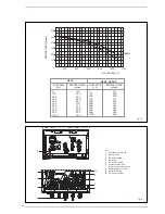
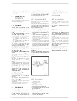
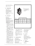
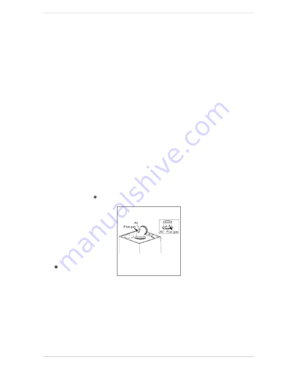
Combustion Check (fig. 23)
Competence to carry out the check of com-
bustion performance.
PLEASE NOTE: BS 6798: 2009 Specifica-
tion fro installation and maintenance of
gas-fired boilers of rated input not excee-
ding 70 kw net advises that:
* The person carrying out a combustion
measurement should have been asses-
sed as competent in the use of a flue gas
analyser and the interpretation of the
results;
* The flue gas analyser should be one mee-
ting the requirements of BS7927 or BS-
EN50379-3 and be calibrated in accor-
dance with the analyser manufacturers
requirements, and
* Competence can be demonstrated by
satisfactory completion of the CPA1 ACS
assessment which covers the use of
electronic por table combustion gas
analysers in accordance with BS7967,
parts 1 to 4.
Conduct a flue gas analysis as detailed in
Appendix 2.
See 4.5.1 "Chimney sweep" for details how
to set the boiler to minimum and maximum
outputs..
4.8.2 Burner
inspection
– Isolate from mains
– Remove case cover
– Isolate gas
– Drop down control case
– Remove ignition and ionisation lead
– Disconnect gas pipe from gas valve to
burner mixing arm,
– Disconnect air sensing tube
– Remove air inlet to fan and disconnect
the fan wiring
– Remove the four nuts securing the bur-
ner to the heat exchanger.
– Carefully lift out the burner.
– Check seals and replace if necessary
– Replace in reverse order
Test for gas tightness.
4.8.3 Combustion
Chamber
Remove any loose debris from the combu-
stion chamber using a soft brush and a
vacuum cleaner.
Take care not to damage the rear insula-
tion panel.
4.8.4 Condensate
Trap
The condensate trap would not normally
require removal during service, but can be
checked whilst the burner assembly is
removed.
Carefully pour water into the heat exchan-
ger and check that it flows freely to the
drain.
Should it require removal, firstly remove
the two wire clips securing the condensate
drain rubber pipe to the heat exchanger
and the condensate trap.
Remove the pipe.
Remove the 1/2” nut securing the conden-
sate trap to the bracket.
Disconnect the drain pipe from the trap.
Clean the trap and refit in reverse order.
Fig. 23


