background image

26

*All installations in England and Wales must be

to Local Authority Building Control (LABC) either directly or through a

Competent Persons Scheme. A Building Regulations Compliance

will then be issued to the customer.

© Heating and Hotwater Industry Council (HHIC)

www.centralheating.co.uk

It is recommended that your heating system is serviced regularly and that the appropriate Service Interval Record is completed.

Service Provider

Before completing the appropriate Service Record below, please ensure you have carried out the service as described in the manufacturer’s instructions. 

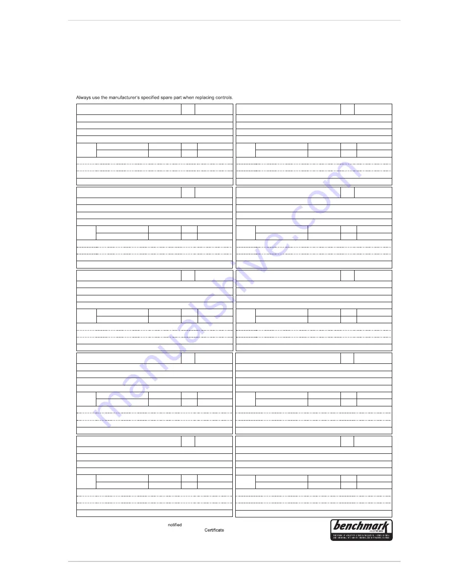
SERVICE RECORD

SERVICE 01

Date:

Engineer name:

Company name:

Telephone No:

Gas safe register No:

Record:

At max. rate:

CO           ppm

AND

CO² %

At min. rate: 

(Where Possible)

CO           ppm

AND

CO² %

Comments:

Signature

SERVICE 02

Date:

Engineer name:

Company name:

Telephone No:

Gas safe register No:

Record:

At max. rate:

CO           ppm

AND

CO² %

At min. rate: 

(Where Possible)

CO           ppm

AND

CO² %

Comments:

Signature
SERVICE 03

Date:

Engineer name:

Company name:

Telephone No:

Gas safe register No:

Record:

At max. rate:

CO           ppm

AND

CO² %

At min. rate: 

(Where Possible)

CO           ppm

AND

CO² %

Comments:

Signature

SERVICE 04

Date:

Engineer name:

Company name:

Telephone No:

Gas safe register No:

Record:

At max. rate:

CO           ppm

AND

CO² %

At min. rate: 

(Where Possible)

CO           ppm

AND

CO² %

Comments:

Signature
SERVICE 05

Date:

Engineer name:

Company name:

Telephone No:

Gas safe register No:

Record:

At max. rate:

CO           ppm

AND

CO² %

At min. rate: 

(Where Possible)

CO           ppm

AND

CO² %

Comments:

Signature
SERVICE 06

Date:

Engineer name:

Company name:

Telephone No:

Gas safe register No:

Record:

At max. rate:

CO           ppm

AND

CO² %

At min. rate: 

(Where Possible)

CO           ppm

AND

CO² %

Comments:

Signature
SERVICE 07

Date:

Engineer name:

Company name:

Telephone No:

Gas safe register No:

Record:

At max. rate:

CO           ppm

AND

CO² %

At min. rate: 

(Where Possible)

CO           ppm

AND

CO² %

Comments:

Signature

SERVICE 08

Date:

Engineer name:

Company name:

Telephone No:

Gas safe register No:

Record:

At max. rate:

CO           ppm

AND

CO² %

At min. rate: 

(Where Possible)

CO           ppm

AND

CO² %

Comments:

Signature
SERVICE 09

Date:

Engineer name:

Company name:

Telephone No:

Gas safe register No:

Record:

At max. rate:

CO           ppm

AND

CO² %

At min. rate: 

(Where Possible)

CO           ppm

AND

CO² %

Comments:

Signature
SERVICE 10

Date:

Engineer name:

Company name:

Telephone No:

Gas safe register No:

Record:

At max. rate:

CO           ppm

AND

CO² %

At min. rate: 

(Where Possible)

CO           ppm

AND

CO² %

Comments:

Signature
Summary of Contents for BRAVA DGT HE 25

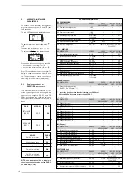
Page 1: ...allation and servicing instructions UK ENSURE THAT THESE INSTRUCTIONS ARE LEFT FOR THE USER AFTER COMPLETION OF THE BENCHMARK SECTION Please read the Important Notice within this guide regarding your boiler warranty 199838 ...

Page 2: ...re recommended Avoid direct contact with sharp edges Avoid contact with any hot surfaces NOTICE Please be aware that due to the wet testing of the appliance there may some residual water in the hydraulic circuit Protect any surfaces carpets or floorings Use a suitable container to catch any water that escape when removing the protective caps from the connections SAFE HANDLING IMPORTANT NOTICE For ...

Page 3: ......

Page 4: ...ndards of installation and commissioning of domestic heating and hot water systems in the UK and to encourage regular servicing to optimi se safety efficiency and performance Benchmark is managed and promoted by the Heating and Hotwater Industry Council For more information visit www centralheating co uk ...

Page 5: ...nd the correct pressure showing on the pressure gauge Is the Auto Air Vent open Has the pump been rotated manually Is the gas supply working pressure correct Is the boiler wired correctly See installation manual Has the customer been fully advised on the correct use of the boiler system and controls Has the Benchmark Checklist in the use and maintenance section of this manual been completed IPX4D ...

Page 6: ...N MERIDIAN HE 30 C are premixed gas con densation thermal modules that employ a microprocessor based technology to con trol and manage all the functions All modu les are compliant with European Directives 2009 142 CE 2004 108 CE 2006 95 CE and 92 42 CE For opti mum installation and operation always fol low the instructions provided in this manual The products manufactured and sold by Sime do not c...

Page 7: ...of the heating expansion vessel bar 1 0 D H W setting range C 10 60 D H W flow rate EN 625 l min 13 4 Continuous D H W flow rate t 30 C l min 14 4 Minimum D H W flow rate l min 2 2 D H W pressure min max bar 0 5 6 0 Exhaust fumes temper at max flow rate 80 60 C C 79 Exhaust fumes temper at min flow rate 80 60 C C 67 Exhaust fumes temper at max flow rate 50 30 C C 51 Exhaust fumes temper at min flo...

Page 8: ...release vent 11 D H W flow switch 12 Water inlet filter 14 Pressure relief valve 15 Water pressure switch 16 Automatic bypass 17 Drain vent 18 Expansion vessel 19 Condensate drain trap 21 D H W isolation valve 22 Gas isolation valve 23 C H flow isolation valve 24 C H return isolation valve 25 D H W sensor SS CONNECTIONS R C H return M C H flow G Gas connection E D H W inlet U D H W outlet S3 Conde...

Page 9: ... 3 C H sensor SM 4 Safety thermostat 5 Ignition electrode 6 Programming clock 7 Primary exchanger 8 Air release vent 9 Limit stat 10 Exhaust temperature sensor 11 Smoke chamber 12 Expansion vessel 13 Air inlet 14 Ionisation electrode 15 Fan 16 Pressure relief valve 17 Air release vent 18 Pump 19 D H W sensor SS NOTE Analogue pressure gauge ...

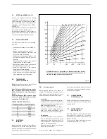
Page 10: ...r ances in fig 1 should be respected The boiler is supplied with a valve pack part number 5184817A The boiler can be filled and pressure tested prior to any electrical supply being connected with the use of the analogue pressure gauge A safety valve set at 3 bar is fitted to the appliance the discharge pipe provided should be extended to terminate safely away from the appliance and where a dis cha...

Page 11: ...y heat exchanger item 8 fig 3 to release any air retained and ensure that all the radiators are vented Top up the system pressure to 1 5 bar Turn on the power supply to the boiler and put the boiler in the Summer mode While in the Summer mode adjust the heating flow temperature to its mini mum 20 degrees Put the boiler into the Winter mode and allow it to ignite Run the boiler in this mode for app...

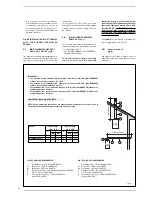
Page 12: ... show a some of examples of the permitted exhausts confi gurations C33 6 5 3 2 C43 3 4 2 x y x y L m H m C13 1 2 1 L m 2 LIST OF ø 60 100 ACCESSORIES 1 Coaxial duct kit L 790 code 8096250 2a Extension L 1000 code 8096150 2b Extension L 500 code 8096151 3 Vertical extension L 140 with coupling code 8086950 5 Tile for joint code 8091300 6 Terminal for roof exit L 1285 code 8091212 includes 8086950 M...

Page 13: ...the appliance or incorrect connec tion of external controls Any fault or compo nent failure due to incorrect connection of external controls is not covered in the warranty 120 183 139 185 185 80 80 1 2 3 CS CA 130 vers HE 35 Fig 7 KEY 1 Adaptor with vent 2 Air intake 3 Exhaust CA Inlet CS Outlet 13 9 C C33 11 10 3 1 1 3 3 7 3 12 12 12 Fig 8 C13 3 2 3 1 14 12 13 12 NOTE Before connecting accessorie...

Page 14: ...M Horizontally from a vertical terminal to a wall 300 mm 12 in N Horizontally from an openable window or other opening 300 mm 12 in P Above an openable window or other opening 300 mm 12 in Q From an adjacent vertical terminal 600 mm 24 in For condensing boilers this distance can be reduced to 25 mm without effecting boiler per formance but it will be necessary to protect the surfaces from the effe...

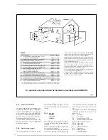
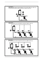
Page 15: ...2 1 BASIC SYSTEM SYSTEM WITH A DIRECT ZONE AND ROOM THERMOSTAT OR WITH A REMOTE CONTROL Code 8092219 KIT EXPANSION REMOTE CONTROL Code 8092240 AND EXTERNAL SENSOR Code 8094101 R M SE TA CR EXP TA R M SE TA1 TA2 TA P2 RL SI RL1 RL2 P1 P 3 BASIC SYSTEM MULTI ZONE SYSTEM WITH PUMP ROOM THERMOSTATS AND EXTERNAL SENSOR Code 8094101 ...

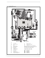
Page 16: ...lve coil VD Divertor valve OP Programming clock SM C H sensor TS Safety thermostat TFU Thermal fuse TL Limit stat FL D H W flow switch SF Exhaust temperature sensor PA Water pressure switch TA Room thermostat SE External sensor optional SS D H W sensor EXP Expansion card remote control optional NOTE Connect a voltage free room thermostat TA to terminals 5 6 after removal of the link CONNECTOR SPAR...

Page 17: ...more than two seconds to enter standby RESET is only available if a re settable error is signalled D H W SET Press the key to display the D H W temperature value set HEATING SET Press the key to display the heating flow temperature value set value not realtive to the remote control DECREASE Pressing this key decreases the value set INCREASE Pressing this key increases the value set 3 LED GREEN ON ...

Page 18: ... 1 20 13 Minimum heating temperature 20 PAR 14 C 1 20 14 Maximum heating temperature PAR 13 80 C 1 80 15 Maximum heating power 30 99 1 99 16 Post circulation time 0 99 10 sec 1 03 17 Pump heating activation delay 0 99 10 sec 1 01 18 Re ignition delay 0 10 Min 1 03 19 Flow meter modulation saturation band 0 99 1 30 29 Anti legionella only D H W tank O Disabled 0 1 Enabled PARAMETERS RE SET PAR DESC...

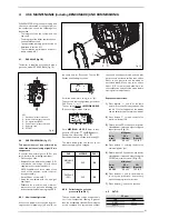
Page 19: ...which guarantees reaction in the case of accidental extinction or lack of gas within one second 3 6 1 Functioning cycle Burner ignition should occur within 10 seconds of the opening of the gas valve If after three attempts the ignition is not detected the boiler will lockout ALL 06 Lack of gas The ignition electrode will discharge for a maximum of 10 seconds If after three attempts the ignition is...

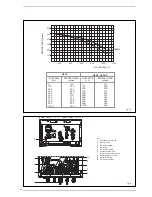
Page 20: ...ZA l h RESIDUA mbar 0 515 100 485 200 480 300 471 400 462 500 445 600 423 700 391 800 352 900 300 1050 222 HE 25 HE 30 HE 30 C Fig 15 Fig 14 RESIDUAL HEAD mbar FLOW RATE l h KEY 1 Condensate drain trap 2 Diverter valve 3 D H W exchanger 4 Gas valve 5 D H W flow switch 6 Pressure relief valve 7 Pump with air release vent 8 Water pressure switch 9 Boiler discharge 10 D H W sensor SS 1 2 3 4 6 5 7 8 ...

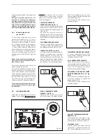
Page 21: ... Exit the parameters section by pressing The table below gives the values to set when the supply gas is changed 4 2 2 Calibrating the gas valve pressures See 4 8 1 This can only be done using a flue gas analy ser If the combustion reading is greater than the acceptable value AND the integrity of the complete flue system and combu stion seals have been verified and the inlet gas pressure has been v...

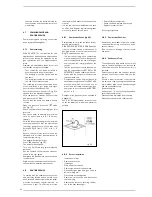
Page 22: ...nel and tilt it forward and be able to access the internal components of the boi ler 4 5 MAINTENANCE fig 20 To guarantee the operation and efficiency of the appliance and to conform to any extended warranty it must be serviced regularly dependant on usage but at least 2 4 x 1 Fig 19 Codice Code 8111862 Modello Model MERIDIAN HE 30 C Matricola Serial n 9999999999 PAR 1 02 METANO 05 GPL PAR 2 13 Fig...

Page 23: ...the pressure detected by the water pressure valve is lower than 0 5 bar the boiler stops and the display shows the alarm AL 02 Increase the system pressure to between 1 0 and 1 2 bar use pressure gauge fig 22 a using the external filling loop The boiler will automatically resume operating C H SENSOR ERROR ALARM 05 When C H sensor SM is open or short circuited the boiler will not function and the d...

Page 24: ...is manual It is the law that a competent person such as a Gas Safe Register registered engineer must carry out any service work 4 8 1 Combustion Check fig 23 Competence to carry out the check of com bustion performance PLEASE NOTE BS 6798 2009 Specifica tion fro installation and maintenance of gas fired boilers of rated input not excee ding 70 kw net advises that The person carrying out a combusti...

Page 25: ... Fitted Not required Thermostatic radiator valves Fitted Not required Automatic bypass to system Fitted Not required Boiler interlock Provided ALL SYSTEMS s instructions Yes What system cleaner was used What inhibitor was used Quantity litres Yes No CENTRAL HEATING MODE measure and record Gas rate m hr OR ft hr Burner operating pressure if applicable mbar OR Gas inlet pressure mbar C Central heati...

Page 26: ...min rate Where Possible CO ppm AND CO Comments Signature SERVICE 04 Date Engineer name Company name Telephone No Gas safe register No Record At max rate CO ppm AND CO At min rate Where Possible CO ppm AND CO Comments Signature SERVICE 05 Date Engineer name Company name Telephone No Gas safe register No Record At max rate CO ppm AND CO At min rate Where Possible CO ppm AND CO Comments Signature SER...

Page 27: ...eads from L to E if meter reads other than infinity there is a fault which should be isolated A detailed continuity check is required to trace the faulty component IMPORTANT These series of checks are the first elec trical checks to be carried out during a fault finding procedure On completion of the service fault finding task which has required the breaking and remaking of electrical connections ...

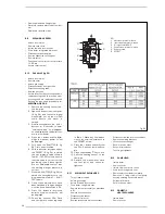
Page 28: ...working inlet gas pressure is correct 7 Close the SHUTTER 5 fig 24 to obtain the second pressure rea ding indicated in Table 1 SHUT TER column 8 Once these adjustments have been obtained a flue gas analysis must be done See section 4 2 2 9 Press the button to return the boiler to minimum output Lo will be displayed 10 Check the analyzer CO2 Ratio and compare to values reported in Table 1 Make any ...

Page 29: ...in boiler using drain vent Remove motor head as 6 15 Remove pin and withdraw the cartridge catching any excess water Refit in reverse order ensure cartridge is locked in position 6 18 WATER PRESSURE SWITCH Isolate boiler Remove cover Isolate flow and return valves Drain boiler using drain vent Remove clip below the switch Disconnect the wiring Lift switch upwards Refit in reverse order 6 19 DHW FL...

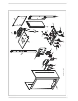
Page 30: ...30 7 EXPLODED VIEWS ...

Page 31: ...31 ...

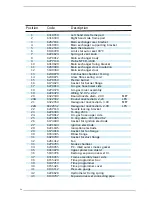
Page 32: ...zzle diam 2 80 MET 20A 6322302 Round nozzle diam 2 20 LPG 21 6322350 Hexagonal nozzle diam 3 80 MET 22A 6322352 Hexagonal nozzle diam 2 90 LPG 22 6267119 Nozzle locking bracket 23 6226403 O ring 2031 24 6278812 Air gas hose upper side 25 6226465 O ring diam 183 83x2 62 26 6174809 Gasket for ignition electrode 27 6221644 Ignition electrode 28 6221645 Ionisation electrode 29 6174816 Gasket for fan f...

Page 33: ...t 63 6317852 Casing 66 6177505 Ball cock 3 4 x 22 67 6177530 Gas cock 3 4 F x 15 68 6177506 Ball cock 1 2 x 15 69 6142330 Quarter bend 1 2 x 15 70 6304766 Control panel 72 6301485 Main PCB 74 6305050 Control panel cover 80 6265651 Plate heat exchanger 81 6281411 Water rate adjuster 15 l min 82 6087329 Motor for Honeywell diverting valve 83 6037509 Water pressure switch 84 6226639 Spring clip 85 61...

Page 34: ...319695 O ring kit 5199630 Complete control panel 6323861 6 pole cable connector 6316253 9 pole Stocko connector 6323856 14 pole cable connector 6319158 4 pole cable connector 6323860 5 pole cable connector 6245374 Circulating pump connector 6285003 Ionisation lead L 1000 Products reference 8111862 Check the correspondence with the boiler data plate Code Description 99 6227036 D H W outlet pipe ...

Page 35: ...f the possibility that UK weather patterns will show more extremes in future due to the effects of global climate change the following guidance updates previous recommendations on condensate drainage pipe installation All other technical requirements for condensate drain installation given in British Standard BS 6798 2009 or in boiler manufacturers installation instructions should still be followe...

Page 36: ...an be removed using a proprietary condensate pump of a specification recommended by the boiler or pump manufacturer The pump outlet should discharge to a suitable internal foul water discharge point such as a an internal soil and vent stack or b an internal kitchen or bathroom waste pipe washing machine waste pipe etc Figure 3 shows a typical connection method A suitable permanent connection to th...

Page 37: ...tion then the connection method shown in Figure 4 should be used together with the measures on insulation etc as described above and shown in the diagram When a rain water downpipe is used as the termination NB only permissible if this downpipe passes to a combined foul and rainwater drainage system an air break must be installed between the condensate drainage pipe and the downpipe to avoid rever...

Page 38: ... for householders on remedial actions which can be taken if a condensate drainage pipe freezes This may result in requests for alteration to condensate drainage pipework in which case the guidance above should be followed In some instances e g where an elderly person s heating needs to be reinstated as an emergency measure condensate drainage pipes may have been cut in order to bypass any blockage...

Page 39: ...ernal soil and vent stack Key 1 Boiler 2 Visible air break 3 75 mm trap 4 Visible air break and trap not required if there is a trap with a minimum condensate seal of 75 mm incorporated into the boiler 5 Soil and vent stack 6 Invert 7 450 mm minimum up to three storeys 8 Minimum internal diameter 19 mm ...

Page 40: ...ired if there is a trap with a minimum condensate seal of 75 mm incorporated into the boiler In this case the 100 mm is measured to the trap in the boiler 5 Sink basin bath or shower 6 Open end of condensate drainage pipe direct into gully 25 mm min below grating but above water level end cut at 45 7 Sink lip 8 Minimum internal diameter 19 mm 9 Pipe size transition 10 Minimum internal diameter 30 ...

Page 41: ...Visible air break at plug hole 3 75 mm sink basin bath or shower waste trap 4 Sink basin bath or shower with integral overflow 5 Open end of condensate drainage pipe direct into gully 25 mm min below grating but above water level end cut at 45 6 Minimum internal diameter 19 mm 7 Pipe size transition 8 Minimum internal diameter 30 mm 9 Water weather proof insulation ...

Page 42: ...42 IND GUIDE INST 10 11 HHIC REF T11 0027BRev8 Figure 3 Connection of a condensate pump typical method NB manufacturer s detailed instructions should be followed ...

Page 43: ...inimum up to three storeys 2 Visible air break 8 Minimum internal diameter 19 mm 3 75 mm trap 9 Pipe size transition point 4 Visible air break and trap not required if there is a trap with a minimum condensate seal of 75 mm incorporated into the boiler 10 Minimum internal diameter 30 mm 11 Water weather proof insulation 5 Soil and vent stack 6 Invert ...

Page 44: ...r drain Key 1 Condensate discharge pipe from boiler 7 Air gap 2 Pipe size transition point 8 68 mm PVCu strap on fitting 3 Water weather proof insulation 9 Minimum internal diameter 19 mm 4 43 mm 90 male female bend 10 Minimum internal diameter 30 mm 5 External rain water pipe into foul water 11 End cut at 45 6 External air break ...

Page 45: ...t required if there is a trap with a minimum condensate seal of 38 mm incorporated into the boiler 5 External length of pipe 3 m maximum 6 Open end of condensate drainage pipe direct into gully 25 mm min below grating but above water level end cut at 45 7 Minimum internal diameter 19 mm 8 Pipe size transition point 9 Minimum internal diameter 30 mm 10 Water weather proof insulation ...

Page 46: ... above or below ground level End cut at 45 3 Diameter 100 mm minimum plastic tube 4 Bottom of tube sealed 5 Limestone chippings 6 Two rows of three 12 mm holes at 25 mm centres 50 mm from bottom of tube and facing away from house 7 Hole depth 400 mm minimum by 300 mm diameter 8 Minimum internal diameter 19 mm 9 Pipe size transition point 10 Minimum internal diameter 30 mm 11 Water weather proof in...

Page 47: ...d to the boiler Is O2 less than or equal to 20 6 and CO2 less than 0 2 VERIFY FLUE INTEGRITY Analyser readings indicate that combustion products and inlet air must be mixing Further investigation of the flue is therefore required Check that flue components are assembled fixed and supported as per boi ler flue manufacturer s instructions Check that flue and flue terminal are not obstructed Is O2 le...

Page 48: ...Cod 6318136 08 2013 Documentation Dpt Sime Ltd 1a Blue Ridge Park Thunderhead Ridge Glasshoughton Castleford WF10 4UA Phone 0845 9011114 Fax 0845 9011115 www sime co uk Email enquiries sime co uk ...

Reviews: