28
– Remove electrode fixing screw
– Carefully remove electrode from bur-
ner
– Replace in reverse order.
6.9 EXPANSION
VESSEL
– Isolate from mains
– Remove case cover
– Isolate flow and return valves
– Drain boiler using fitted drain vent
– Disconnect expansion pipe
– Remove expansion securing nut
– Remove vessel
– Check new vessel for correct pressure
1-1.25 bar
– Refit in reverse order
6.10
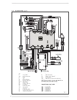
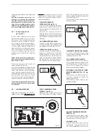
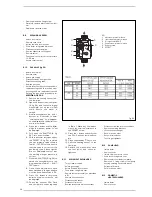
GAS VALVE (fig. 24)
– Isolate from mains
– Remove cover
– Isolate gas supply
– Disconnect leads from gas valve
– Disconnect sensing tube
– Remove gas valve
– Refit in reverse order ensuring seals are
replaced as required fit in reverse order
ensuring seals are replaced as required
– Setting the gas valve procedure for
MERIDIAN HE 30 C
:
1. Remove the heating sensor from
the flow pipe.
2. Open the downstream test point
(4 fig. 24) and connect a digital
manometer set on the mmH
2
0
scale. Ensure the meter is
zeroed.
3. Simultaneously press the - and +
buttons for 5 seconds to enter
“chimney sweep”. “Lo” will appear
on the display and the boiler runs
at minimum power.
4. Press the + button and the boiler
will go to maximum power “Hi” will
be displayed.
5. Fully open the SHUTTER (5 fig.
24) - turn anti clockwise.
6. With the shutter fully open, adjust
the OFF-SET (6 fig. 24) to obtain
the first pressure value shown in
Table 1 - OFF-SET column, ensure
that the value is correct for the
gas being used. If these figures
are not obtainable, confirm that
the working inlet gas pressure is
correct.
7. Close the SHUTTER (5 fig. 24) to
obtain the second pressure rea-
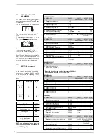
ding indicated in Table 1 – SHUT-
TER column.
8. Once these adjustments have
been obtained, a flue gas analysis
must be done. See section 4.2.2.
9. Press the - button to return the
boiler to minimum output “Lo” will
be displayed.
10. Check the analyzer CO
2
/Ratio
and compare to values reported
in Table 1. Make any final adjust-
ments by small adjustments to
the OFF-SET screw.
11. Press the + button and verify that
the CO
2
/Ratio has remained sta-
ble.
12. Press the Standby
key to exit.
13. Refit the heating sensor to the
flow pipe.
14. Remove the manometer, close
the test point, and check for
tightness.
6.11
MAIN HEAT EXCHANGER
– Turn off power supply
– Isolate gas supply
– Isolate flow and return valves
– Drain boiler using drain vent
– Remove burner assembly as described
in 6.1
– Remove flue connection
– Disconnect flue sensor
– Disconnect limit stat
– Remove condensate drain connections
– Disconnect flow and return connections
– Remove two fixing brackets
– Lift out heat exchanger
– Refit in reverse order
– Recommission boiler
– Test for gas tightness.
6.12 PUMP
HEAD
– Isolate boiler
– Remove cover
– Isolate flow and return valves
– Drain boiler using drain vent
– Remove electrical lead from pump
– Remove 4 x fixing screws from pump
housing catching any excess water
– Pull pump forward
– Refit in reverse order
6.13 DOMESTIC
HEAT EXCHANGER
– Isolate boiler
– Remove cover
Fig. 24
KEY
1
Upstream pressure intake
2
Intermediate pressure intake
3
Air signal inlet (VENT)
4
Downstream pressure intake
5
Capacity step
6
OFF-SET
1
2
3
4
5
6

