10
Where no specific instructions are given,
the installation should be in accordance
with the relevant recommendations in the
current editions of the following British
St andards and Codes of Practice: BS
5440-1, BS 5440-2, BS 5449, BS 5482
(propane installations), BS 5546, BS 6700,
BS 6798, BS 6891, Institute of Gas Engi-
neer document IGE/UP-7, BS 7074 (expan-
sion vessel), and to other relevant British
Standards or code of Practice as neces-
sary. It is a
Statutory Requirement
that
the installation conforms to the appropria-
te Building Regulations either The Building
Regulations, The Building Regulations (Sco-
tland), Building Regulations (Northern Ire-
land), the Water Fitting Regulations or
Water Byelaws in Scotland, and the cur-
rent I.E.E Wiring Regulations. When hand-
ling, due consideration should be given to
the appliance weight. If the appliance is not
to be installed immediately it should be sto-
red in a clean dry place.
2.1
BOILER ROOM
The
“DEWY 30/130 HE FS”
version boilers
can be installed in any domestic environ-
ment
without any location restrictions,
other than the load bearing capacity of the
floor where the appliance is to be sited,
(consult section 1.3 for weight),
or “Combu-
stion”
air requirements. However, suitable
clearances for maintenance and servicing
should be provided, see fig. 1.
2.2
CONNECTING UP SYSTEM
Before connecting the boiler it is recom-
mended that the system is flushed in
accordance with BS7593. When making
the hydraulic connections, make sure that
the dimensions indicated in fig. 1 are
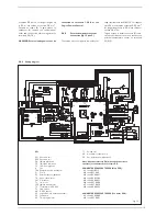
respected. Fit the supplied; pressure redu-
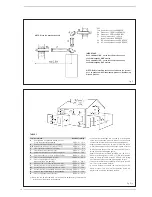
cing valve (30 fig. 2), check valve (31 fig. 2)
and expansion relief valve assembly (32 fig.
2) with its associated tundish (33 fig. 2), in
the D.H.W. supply to the appliance, see fig.
2 and fig. 4 for details. It is important that
no isolating valve is fitted between the
expansion relief valve and the inlet to the
D.H.W. tank. Any additional D.H.W. drain
down cock fitted should be positioned as low
as possible to ensure that at least 80% of
the D.H.W. tank’s capacity can be drained.
If installed in a Hard Water area, then a sui-
table device should be fitted to treat the
mains supply to the appliance (Contact your
Water Distribution Company for advice on
suitable devices).
The pressure relief
discharge pipes must be connected to
ensure safe discharge.
The gas connec-
tion must be made using seamless steel
pipe (Mannesmann type), galvanized and
with threaded joints provided with
gaskets, excluding three-piece connec-
tions, except for initial and end connec-
tions. Where the piping has to pass throu-
gh walls, a suitable insulating sleeve must
be provided. When sizing gas piping, from
the meter to the boiler, take into account
both the volume flow rates (consumption)
in m
3
/h and the relative density of the gas
in question. The sections of the piping
making up the system must be such as to
guarantee a supply of gas sufficient to cover
the maximum demand, limiting pressure
loss between the gas meter and any appa-
ratus being used to not greater than 1.0
mbar for family II gases (natural gas). An
adhesive data plate is stuck inside the front
panel; it contains all the technical data iden-
tifying the boiler and the type of gas for
which the boiler is arranged.
2.2.1
Connection of condensation water trap
To ensure safe disposal of the condensate
produced by the flue gases, reference
should be made to BS6798:2009. The boi-
ler incorporates a condensate trap which
has a seal of 75 mm, therefore no additio-
nal trap is required. The condensate should
ideally be discharged internally into an inter-
nal waste pipe(washing machine/sink
waste) or a soil pipe to avoid the risk of free-
zing. External pipe runs should be avoided,
but if it is necessary, the pipework should be
at least 32 mm and protected from the risk
of freezing with a waterproof insulation and
the length kept to a minimum and not
exceeding 3 m termination should be into
an external gully or purpose made
soakaway. We recommend that the con-
densate drain at the boiler is in 20 mm sol-
vent weld pipe with a socket covering the
connection to the trap. Alternatively a suita-
ble hose can be secured to the trap and ter-
minated as required.
NOTE: All pipework must have a continuous
fall from the boiler and must be resistant to
corrosion by condensate, copper or steel is
NOT suitable. It should be noted that the
connection of a condensate pipe to a drain
may be subject to local building control
requirements.
2.2.2
Filter on the gas pipe
The gas valve is supplied with an inlet filter,
however, this may not be adequate to entrap
all the impurities in the gas or in gas main
pipes. To prevent malfunctioning of the valve
it may be necessary toinstall an adequate fil-
ter on the gas pipe.
2.2.3
Filling the Condensate Trap
The condensate trap can be filled, prior to fit-
ting the flue by carefully pouring approxima-
tely 1 litre of water into the centre of the
exhaust terminal of the main heat exchanger.
2.2.4
Discharge Pipes and fittings
The position of any tundish must be visible to
the occupants and any tundish, drain valve
and discharge pipe and must be sited away
from any electrical components. The con-
nections to the expansion relief valve and
temperature and pressure relief valve
should not be used for any other purpose.
See fig. 4 for example of the discharge
pipe(s) for the temperature and pressure
relief valve, and expansion relief valve termi-
nations.
NOTE: it is permitted to connect discharge
pipes together provided that the joint pipe is
sized to accommodate the combined flow.
2.2.5 Expansion Vessel (C.H. only)
C.H. EXPANSION VESSEL – The integral
expansion vessel is pre-charged to a pres-
sure of 1.0 bar, which should be checked
before the C.H. water system is filled.
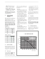
This vessel is suitable for correct operation
of system capacities up to 82 litre capacity.
If the actual C.H. system volume is greater,
then an additional vessel must be fitted to
the system.
For systems where the volume is greater,
the additional expansion vessel volume can
be determined by multiplying the volume in
excess of that which can be accommoda-
ted by the appliance by the factor 0.901.
BS 7074 gives further details regarding
C.H. expansion vessel sizing.
2.3
CHARACTERISTICS
OF C.H. FEEDWATER
– All recirculatory systems will be subject
to corrosion unless an appropriate
water treatment is applied. This means
that the efficiency of the system will
deteriorate as corrosion sludge accu-
mulates within the system, risking dam-
age to pump and valves, boiler noise
and circulation problems.
– For optimum performance after instal-
lation this boiler and its associated cen-
tral heating system must be flushed in
accordance with the guidelines given in
BS 7593 “Tr eatment of wat er in
domestic hot water central heating sys-
tems”.
– Sime Ltd recommend only the use of
FERNOX products for the flushing and
final treatment of the system water.
This is particularly important in hard
water areas. Failure to flush and add
inhibitor to the system may invalidate
the appliance warranty. Artificially soft-
ened water must not be used to fill the
heating system.
Failure to flush and add inhibitor to
the system may invalidate the appli-
ance warranty.
– It is important to check the inhibitor
concentration after installation, system
modification and at every service in
accordance with the manufacturer’s
instructions (Test kits are available from
inhibitor stockists).
2
INSTALLATION


