2.4.
FILLING AND COMMISSIONING
2.4.1 D.H.W.
circuit
Before filling the D.H.W. system, ensure
appliance selector knob is in the “Off” posi-
tion, then open the hot water tap nearest
the appliance.
Open the D.H.W. supply isolating valve to
the appliance, once water starts to flow
from the tap close it, and then open and
close each hot water tap in turn to ensure
t hat all t he air is r emoved fr om t he
pipework. Open the hot water tap furthest
away from the appliance and let water flow
for about 10 minutes, or for sufficient time
to flush out the system. Check for leaks.
2.4.2 C.H.
circuit
Once the D.H.W. circuit is commissioned
the C.H. circuit can be filled via the internal
filling loop (if fitted), or via any external
arrangement. Ensure both the D.H.W. and
C.H. temperature controls are set to mini-
mum, and that there is no room thermo-
stat demand. Turn on the electrical supply
to the appliance (see Section 2.8), and turn
the selector knob to the summer position.
To use the internal filling loop, ensure that
the flexible hose is attached to both valves,
then open the C.H. isolating valve and then
open the D.H.W. double check isolating
valve, (See fig. 2).
Once the green
“1 bar”
led lights up close
both isolating valvesensure that all the
radiators are vented, continue opening the
filling loop to maintain the 1 bar pressure.
When all the radiators are vented ensure
the pressure is at 1 bar. then disconnect
the flexible hose from the D.H.W. double
check isolating valve. Check for leaks and
free rotation of the circulating pumps.
2.5
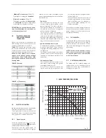
COAXIAL DUCT ø 60/100
Prior to fitting the flue system the conden-
sate trap can be filled see 2.2.3. The coaxial
suction and discharge pipes are supplied in
a special kit (that can be purchased separa-
tely) along with assembly instructions. The
diagrams of fig. 5 illustrate some examples
of different types of discharge options
allowed and the maximum lengths that can
be reached. It is essential that a flue gas
analysis test point is made available directly
above the boiler.
2.5.1
Coaxial duct accessories
The maximum flue length using 60/100
ducts and accessories must not exceed 2.8
metres.
2.5.2
Positioning the outlet terminals
The outlet terminals for forced-draught
appliances may be located in the external
perimeter walls of the building.
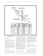
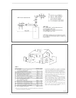
To provide some indications of possible solu-
Fig. 4
11


