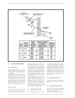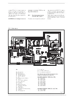
tions,
Table 1
gives the minimum distances
to be observed, with reference to the type
of building shown in fig. 5/a.
2.6
SEPARATE PIPES ø 80
A special kit may be used to separate the
flue gas outlet from the air intake. The
intake may be installed to the right or left of
the flue gas outlet. It is essential that a flue
gas analysis test point is made available
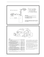
directly above the boiler. Refer to fig. 8 for
positioning.
The maximum overall length of
the intake and exhaust ducts depends on
the head losses of the single fittings
installed (excluding the doublers) and
must not be greater than 15,5 mm H
2
O.
For head losses in the fittings, refer to
Table
2
.
2.6.1
Separate pipe accessories
Kit code 8089911 is supplied for this pur-
pose (fig. 9).
2.8
ELECTRICAL CONNECTION
Wiring external to the appliance must be in
accordance with the current I.E.E Wiring
regulations (BS 7671) for electrical installa-
tion and any local regulations, which apply.
Connection to the mains supply must facili-
tate complete electrical isolation of the
appliance. A 3A fused double pole switch
having a 3 mm contact separation in both
poles and serving only the appliance (and its
external controls) may be used.
The boiler is supplied with an electric cable.
15
5
Ø 80
Ø 80
10
5
P
L
CA
K
Z
CS
KEY
CA
Inlet
CS
Outlet
Fig. 8
DEWY 30/130 HE FS
K mm
348
L mm
263
P mm
230
Z mm
315
1
2
3
4
5
3
KEY
1 Blind flange
2 Flue gas duct flange
3 Fixing screw
4 Gasket ø 125/95
5 Intake duct collar
Fig. 9
TABLE 2
Accessories ø 80
Head loss (mm H
2
O)
Inlet
Outlet
Roof outlet
90° elbow MF
0.30
0.50
–
45° elbow MF
0.20
0.40
–
Extension L. 1000 (horizontal)
0.20
0.40
–
Extension L. 1000 (vertical)
0.30
0.30
–
Outlet terminal
–
0.40
–
Inlet terminal
0.10
–
–
Doubler fitting
0.30
–
–
Roof outlet terminal L. 1381
–
–
0.60
13


