of section 0.25 mm
2
, for longer lengths up
to 50 m use cables of section 0.5 mm
2
.
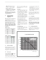
Connect as shown (2). To gain access to
connector (3) remove the control panel
cover and connect the climate regulator to
terminals CR (7-8).
WARNING: External voltage must not be
connected to terminals 1-2-3-4 of the
"Logica Remote Control".
2.8.3
External temperature sensor
connection (fig. 12 pos. C)
The cables must comply with low safety vol-
tage requirements of EN 60730. For lengths
up to 25 m, use cables of section 0.25 mm
2
,
for longer lengths up to 50 m use cables of
section 0.5 mm
2
.
To gain access to boiler connector (3) remo-
ve the control panel cover and connect the
external temperature sensor to terminals
SE (9-10).
J7
J6
J5
J4
J3
J2
J1
J10
J9
J8
J1
J2
2.8.4
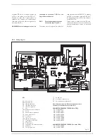
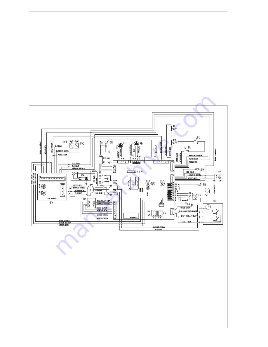
Wiring diagram
Fig. 13
KEY
EV1 Gas valve coil
EV2 Gas valve coil
EA
Ignition electrode
ER
Ionisation electrode
TS
100°C safety stat
V
Fan
TPA Water pressure transducer
PI
Pump
SE
External sensor (optional)
TA
Room thermostat
SM
C.H. sensor
TL
Limit stat
TRA Ignition transformer
TR
Transformer 230 - 24V
FL
Flow switch
SB
D.H.W. sensor
CR
Logica Remote Control (optional)
SV
Fan board
OP
Time programmer
TF
Smoke stat
PB
Hot water cylinder pump
PR
Recirculation pump (optional)
Note: Room thermostats (TA), with voltage free(clean
contacts) are connected to terminals 5-6.
CONNECTOR SPARE PART CODES (Main PCB):
J1
code 6316215
J2
code 6278613
J3
code 6299961
J4
code 6293564
J5
code 6299921
J6
code 6278699
J7
code 6278636
J8
code 6098305
CONNECTOR SPARE PART CODES (Fan driver PCB):
J1
code 6260996
J2
code 6278661
15


