Fonder
ie Sime S.p.A
. - V
ia Garbo, 2
7
- 3
7
0
45 Legnago (V
er
ona) - T
el. +39-0
4
42-63
1111
-
F
a
x
+39-0
4
42-63
1
292 - www
.sime.it
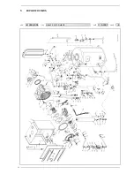
POSITION
CODE
DESCRIPTION
MODEL
N
O
TE
COD.
T
YPE
D
A
TE
P
A
GE
•
R
ecommended s
tock par
ts - C
o
m
ponenti da t
ener
e a scor
ta
POSITION
CODE
DESCRIPTION
MODEL
N
O
TE
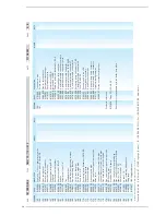
1
626603
4
Sealed chamber r
ear panel
2
6266
1
2
1
Sealed chamber side panel
3
•
623
1
3
3
1
D.H.W
. t
a
nk sensor
4
6
1
1
93
43
Cap f
or s
tat hole
5
6
1
79200
Holder com
ple
te wit
h
locking nut
6
•
62
7
720
1
W
at
er tr
ap
7
2
0
1
3302
F
a
s
tener f
or self t
apping scr
ew
8
6280500
3-way
s
junct. wit
h pr
ess. t
e
s
t nipple
9
6
1
46303
Br
ass N
ut 1/8”
1
0
5003
1
0
5
Glass-lined H.W
. cy
linder l. 1
3
0
1
1
6
1
79
1
0
2
D
rain cock 1/2”
1
2
62
7
730
1
C
ondensat
e dr
ainage pipe
1
3
62
7
4303
U
p
s
tr
eam side mixer par
t
1
4
6226
42
7
O-r
ing 1
5
6
1
5
62
7
430
4
D
owns
tr
eam side mixer par
t
1
6
62
7
4
1
0
5
Bur
ner nozzle ø 6,00 natur
al gas
1
6
A
6
2
7
4
1
0
4
Bur
ner nozzle ø 4,30 LPG
1
7
6226
428
O-r
ing 1
1
5
1
8
6
1
7
480
4
Gaske
t f
or f
an f
lange
1
9
6
1
7
480
7
Gaske
t f
or downs
tr
eam side mixer par
t
20
•
626
1
4
0
1
F
an R
G
1
30/0800-36
1
2
2
1
6
1
46
7
1
3
Limit s
tat
22
62
78303
Pr
emix bur
ner
23
6028
703
Gaske
t f
or duct f
lange
2
4
6083052
Duct f
lange
25
20302
40
Te
flon gaske
t Ø 1
7x2
4x2
26
62
7
7
40
1
Pipe connecting gas val
ve-mixer
2
7
203022
7
Gaske
t Ø 1
2x1
8x2
28
6
1
4630
1
B
rass nut 1/2”
29
622
7
4
1
3
Heat exchanger inle
t pipe
30
622
7
4
1
4
Heat exchanger outle
t pipe
3
1
2030228
Gaske
t Ø 1
7x2
4x2
32
6
1
46302
Br
ass nut 3/4”
33
62
7
7800
Pipe connecting air vent
3
4
2030226
Gaske
t Ø 1
0,2x1
4,8x2
35
•
6
0
1
72
1
0
Manual air vent 1/4”
36
•
5
1
8
3
720
R
ect
ang. expansion vessel 1
0
l. 3/8” M
3
7
629290
1
Sealed chamber suppor
ting br
acke
t
38
•
623
1
3
5
1
Plunged sensor
39
•
60220
1
0
Sensor gaske
t
40
629
1
900
C.H. r
e
tur
n manif
old
4
1
629
1
8
1
0
C.H. f
low manif
o
ld
42
629
7
400
Tee joint M 1/2”x1
6
43
•
6
0
40202
Pr
essur
e r
elief val
ve 1/2” 3 bar
4
4
60
733
1
5
Expansion vessel f
ixing br
acke
t
45
1
0
1
0
2
1
3
Condensat
e dr
ainage r
ubber pipe
46
2000
7
1
6
Scr
ew T
.C.B. M4x8
4
7
62925
1
0
Right r
ear fr
ame par
t
48
62926
1
0
Lef
t r
ear fr
ame par
t
49
•
622
1
6
1
7
Ionisation electr
ode
50
62586
1
3
Sealed chamber LH side r
ear suppor
t
5
1
6
1
7
4
8
1
0
Gaske
t f
or ionisation electr
ode
52
•
6226
4
1
2
O-r
ing 3068
53
•
622
1
6
1
6
Ignition electr
ode
5
4
•
6
2
73603
W
a
ter pr
essur
e tr
ansducer
55
603
7580
W
a
ter pr
essur
e r
educer 3/4”
56
•
625
4605
Gr
undf
os cir
culating pum
p UPS 1
5-60
5
7
•
6
0
1
3
1
00
A
u
tomatic air vent 3/8”
58
2030229
Gaske
t Ø 22x30x2
59
622
7
656
Pipe connecting expansion vessel
60
629300
1
Boiler fr
ame-D.H.W
. t
ank f
ixing br
ack
.
6
1
62
1
5
8
1
4
Pipe conn. exch. f
low
-wat
er
fl
ow switch
62
•
6
1
4930
4
Flow wat
e
r switch
63
•
6
1
4
6
7
0
1
1
00°
C saf
e
ty s
tat
6
4
•
6
2
43809
Honeywell gas val
ve type VK8
1
1
5V
65
6235802
Pr
essur
e t
e
s
t point M5
66
6
1
95206
Gas inle
t pipe
6
7
•
6
1
7
4809
Gaske
t f
or ignition electr
ode
68
62586
1
4
Sealed chamber RH side r
ear suppor
t
69
•
6226
40
7
O-r
ing 1
30 ø 22,22x2,62 XP70
70
62
1
660
7
G
as shutt
er 1/2”
7
1
62
7
750
4
Pipe conn. gas val
ve-sealed chamber
72
6023
1
0
0
P
ressur
e t
e
s
t nipple Ø 1/8”
73
6265850
5 way
s
wat
er collect
or
7
4
62295
1
5
Fixing nut 1/2”x1
6 OT
75
200
4
1
1
0
Self t
apping scr
ew T
CB 8Px1/2” Zn
38
1
0009/505
DEWY 30/1
30 HE FS
3
1
.1
0.200
7
4/6
35

