background image

Fonder

ie Sime S.p.A

. - V

ia Garbo, 2

7

 - 3

7

0

45 Legnago (V

er

ona) - T

el. +39-0

4

42-63

1111

 -

 F

a

+39-0

4

42-63

1

292 - www

.sime.it

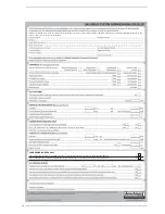
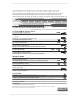
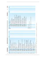
POSITION

CODE

DESCRIPTION

MODEL

N

O

TE

COD.   

T

YPE

D

A

TE

P

A

GE

 R

ecommended s

tock par

ts - C

o

m

ponenti da t

ener

e a scor

ta

POSITION

CODE

DESCRIPTION

MODEL

N

O

TE

7

6

628

1

600

Contr

ol panel 

7

7

62

73200

Guidelight - 1

2

 way

s

 out

78

62

7320

1

Guidelight - 6 way

s

 out 

79

620

1

5

0

1

Tr

immer spindle Ø 5 

80

620

1

502

Tr

immer spindle Ø 6 

8

1

6230683

Main PCB wit

h

 ignition

82

620

1

503

Select

or spindle

83

6

2

4

0

703

Tr

ansf

or

mer 230/2

4V 

8

4

22

1

1

6

1

0

Ear

th

 f

a

s

ton

85

626050

1

F

an dr

iver PCB

86

22

1

3230

Spacer h=6.4

8

7

620

1

5

0

4

Tr

immer spindle Ø 5 L=3

4

88

628

1

800

Contr

ol panel pr

o

tecting cover

89

628

1

900

R

oom s

tat cover 

90

623092

1

Knob Ø 40 

9

1

628

1

700

Flap door 

92

622889

1

Sealed chamber fr

ont panel

93

6282000

Flap door t

ap 

9

4

60

40208

Pr

essur

e r

elief val

ve 

95

62

7896

4

N

ut f

or exchanger f

lange

96

62809

4

1

Casing r

ight hand side panel

9

7

628

1

0

4

1

Casing lef

t hand side panel 

98

2003000

Pin M5 Zn 

99

62808

7

1

Casing fr

ont door 

1

0

0

2

0

1

5000

Spr

ing clip M0/A8 

1

0

1

6

2

78850

Com

ple

te f

lange f

or main exchanger

1

0

2

6280550

Cap f

or 3-way

s junction 

1

0

3

6269005

Combus

tion chamber r

ear insulation

1

0

4

6

2

78993

Main exchanger body 

1

0

5

6

2

48850

Gaske

t f

or smoke chamber

1

0

6

6

2

7

8

700

Smoke chamber 

1

0

7

6

2

78962

Smoke chamber f

ixing scr

ew

1

0

8

6266

7

4

1

F

ront lower panel 

1

0

9

6

1

7

48

1

3

Gaske

t f

or peephole 

1

1

0

6020

1

0

2

G

lass f

or peephole

1

1

1

6

2

78965

O-r

ing ø 223x23

1x4

1

1

2

6

2

78966

Glass f

ibr

e sealing cor

d Ø 6

1

1

3

626900

4

Combus

tion chamber door insulation

1

1

4

6

1

7

4808

Gaske

t f

or bur

ner f

lange

1

1

5

6

2

78963

Bur

ner f

ixing scr

ew 

1

1

6

6

2

7896

1

Comb. chamber r

ear insul. f

ixing scr

ew

1

1

7

6

2

78960

Comb. chamber r

ear insul. f

ixing plat

e

1

1

8

6

1

205

1

1

Nipple 3/4”x3/4” OT 

1

1

9

622660

1

Spr

ing f

or heat exchanger connection

1

2

0

6

1

6

3

1

02

Gas val

ve f

lange c/w br

ass nut 3/4” 

1

2

1

5002

40

4

Bulb holder 1/2” Ø 7x8x400

1

2

2

6

1

00202

Ogive f

or pipe Ø 1

5


1

2

3

6269

405

Tundish 

1

2

4

6

1

6

8

4

0

1

Locking nut f

or pipe Ø 1

5


1

2

5

6292

40

1

Pipe conn. exchanger

-r

e

tur

n manif

o

ld

1

2

6

6

2

1

58

1

5

Pipe conn. w

. f

low switch-f

low manif. 

1

2

7

6292

1

0

3

F

ir

s

t zone C.H. f

low pipe 

1

2

8

6098305

Ignition tr

ansf

or

mer

1

2

9

626

7

1

02

Contr

ol panel suppor

ting br

acke

t

1

3

0

6

1

895

4

7

Expansion vessel suppor

ting br

acke

1

3

1

6

1

895

49

Gas pipe suppor

ting br

acke

1

3

2

6

1

895

48

W

a

ter tr

ap suppor

ting br

acke

1

3

3

2000206

Scr

ew M4 x 25 

1

3

4

200050

4

Scr

ew M5 x 70 

1

3

5

6258305

D.H.W

. cy

linder f

lange Ø 1

9

6

1

3

6

6

1

5

7

6

2

4

Pr

essur

e r

elief val

ve dr

ain pipe

1

3

7

6052

702

Flange oval gaske

t

1

3

8

62

45

1

0

5

D.H.W

. expansion vessel l. 4

1

3

9

622

7

6

5

7

Pipe connecting D.H.W

. expans. vessel 

1

4

0

6029002

Pr

essur

e r

elief val

ve 1/2” - 7 bar

1

4

1

6

1

5

7

6

1

6

Pr

essur

e r

elief val

ve dr

ain pipe

1

4

2

6

0

7

2

706

Magnesium anode Ø 2

1

 L=300

1

4

3

6229550

Plug 3/4” 

1

4

4

2

0

4

1

032

Plug 1/2” 

1

4

5

2

0

4

1

080

Plug 1” 

1

4

6

6282

1

0

3

Section f

or casing t

op cover L=33

7

1

4

7

2

0

1

330

4

F

as

tener f

or self t

apping scr

ew 

1

4

8

628

1

335

R

ear panel

1

4

9

200

4

1

80

Self-t

apping scr

ew T

CB 8SPx3/4” 

1

5

0

6229500

Plug 1/2” 

1

5

1

628

4

7

2

1

R

ear casing cover 

38

1

0009/505

DEWY 30/1

30 HE FS

3

1

.1

0.200

7

5/6

37

Summary of Contents for Dewy 130 HE FS

Page 1: ...UK Dewy 30 130 HE FS Installation and servicing instructions PLEASE LEAVE THIS INSTRUCTION WITH THE USER ...

Page 2: ...er at the base Be physically capable Use personal protective equipment as appropriate e g gloves safety footwear During all manoeuvres and handling actions every attempt should be made to ensure the following unless unavoidable and or the weight is light Keep back straight Avoid twisting at the waist Always grip with the palm of the hand Keep load as close to the body as possible Always use assist...

Page 3: ......

Page 4: ...ndards of installation and commissioning of domestic heating and hot water systems in the UK and to encourage regular servicing to optimi se safety efficiency and performance Benchmark is managed and promoted by the Heating and Hotwater Industry Council For more information visit www centralheating co uk ...

Page 5: ...ronic control card Purge the system bleeding off the air present in the gas pipe by operating the pressure relief valve on the gas valve inlet Check that the syphened drip is fully filled with water If necessary fill it via the special opening Ensure that the Benchmark checklist in the use and maintenance section of this manual is completed Please refer to commissioning instructions for filling in...

Page 6: ... 1109 1229 70 1349 140 300 300 828 846 Fig 1 SERVICE CLEARANCES ABOVE THE APPLIANCE CASING 300 mm AT THE R H S 300 mm AT THE L H S 300 mm IN FRONT OF THE APPLIANCE 700 mm ACCESS TO THE CONNECTIONS AT THE REAR OF THE BOILER MUST BE PROVIDED CONNECTIONS R Zone 1 system return 3 4 UNI ISO 228 1 R1 Zone 2 system return optional 3 4 UNI ISO 228 1 R2 Zone 3 system return optional 3 4 UNI ISO 228 1 M2 Zo...

Page 7: ... D H W tank capacity l 120 D H W expansion vessel l 4 D H W expansion vessel charge pressure bar 3 5 D H W tank heating time between 15 and 60 C min 18 7 Recuperation time between 25 and 55 C min 9 40 Recuperation time to raise 70 of volume to 60 C min 14 49 D H W expansion relief valve setting bar 6 Combined temperature pressure relief valve setting bar 7 Combined temperature pressure relief valv...

Page 8: ...r pocket SB 17 Cylinder 18 Sacrificial Anode 19 D H W temperature pressure relief 20 Filling loop optional cod 8091810 21 D H W expansion vessel 22 Water pressure transducer 23 System pressure relief valve 24 Condensation trap 25 Limit stat 85 C 26 100 C safety stat 27 System delivery manifold 28 System return manifold 29 Tundish 30 Pressure reducing valve 31 Single check valve 32 Expansion relief...

Page 9: ...nsformer 16 Ionisation electrode 17 Main exchanger 18 Ignition electrode 19 Control panel 20 Fan 21 Heating sensor SM 22 100 C safety thermometer 23 System pressure relief valve 24 Water pressure transducer 25 Non return valve 27 Hot water cylinder pump 28 Flow switch assembly 31 Drain vent 32 Drain vent 33 Zone 2 heat pump optional 34 Zone 2 single acting valve optional 35 Zone 3 single acting va...

Page 10: ...r a soil pipe to avoid the risk of free zing External pipe runs should be avoided but if it is necessary the pipework should be at least 32 mm and protected from the risk of freezing with a waterproof insulation and the length kept to a minimum and not exceeding 3 m termination should be into an external gully or purpose made soakaway We recommend that the con densate drain at the boiler is in 20 ...

Page 11: ...H isolating valve and then open the D H W double check isolating valve See fig 2 Once the green 1 bar led lights up close both isolating valvesensure that all the radiators are vented continue opening the filling loop to maintain the 1 bar pressure When all the radiators are vented ensure the pressure is at 1 bar then disconnect the flexible hose from the D H W double check isolating valve Check f...

Page 12: ...into dwelling 1 200 mm 48 in K Vertically from a terminal on the same wall 1 500 mm 60 in L Horizontally from a terminal on the same wall 300 mm 12 in M Horizontally from a vertical terminal to a wall 300 mm 12 in N Horizontally from an openable window or other opening 300 mm 12 in P Above an openable window or other opening 300 mm 12 in Q From an adjacent vertical terminal 600 mm 24 in TABLE 1 No...

Page 13: ... external to the appliance must be in accordance with the current I E E Wiring regulations BS 7671 for electrical installa tion and any local regulations which apply Connection to the mains supply must facili tate complete electrical isolation of the appliance A 3A fused double pole switch having a 3 mm contact separation in both poles and serving only the appliance and its external controls may b...

Page 14: ...control panel cover and connect the room stat to the terminals TA 5 6 after having removed the jumper The thermostat or timer thermostat must be class II as specified by standard EN 60730 1 clean contact WARNING Applying mains voltage to the terminals of conector 3 will irreparably damage the control board Make sure that any connections to be made are not carrying mains voltage 2 8 2 Logica Remote...

Page 15: ...nsor to terminals SE 9 10 J7 J6 J5 J4 J3 J2 J1 J10 J9 J8 J1 J2 2 8 4 Wiring diagram Fig 13 KEY EV1 Gas valve coil EV2 Gas valve coil EA Ignition electrode ER Ionisation electrode TS 100 C safety stat V Fan TPA Water pressure transducer PI Pump SE External sensor optional TA Room thermostat SM C H sensor TL Limit stat TRA Ignition transformer TR Transformer 230 24V FL Flow switch SB D H W sensor CR...

Page 16: ...mer winter switch over Controllable maximum delivery tempera ture limit specifically for floor plants Limitation of increase in pre set delivery temperature Anti freeze protection for buildings Hourly programming of the tank unit temperature on two levels comfort and reduced Domestic hot water control with nominal value requirement and enable Connection to room sensor or switching of operating reg...

Page 17: ...set function disabled If the switch off time optimisation is active value 0 the Logica Remote Control modifies the pre set time until it finds the optimum switch off time 55 56 57 58 59 60 Antifreeze protection Pre set ambient temperature value Summer Winter switch over temperature Type of control 0 with ambient influence 1 without ambient influence Influence of ambient temperature Heating takes p...

Page 18: ...ue set with user parameter n 3 In the reduced areas of heating the temperature of the boiler unit is regulated to the value set with parameter n 61 of the service level 2 service disconnected 3 second daily programme 8 Every day of the week the temperature of the hot water is set according to programme 8 In this case there is a single programming for all the days of the week and three time zones a...

Page 19: ...d so as to obtain a pressure of approx 3 mbar at the burner for methane gas and 7 mbar for propane gas G31 To increase pressure turn the trimmer clockwise to reduce pressure turn the trimmer counterclockwise The slow ignition pressure level can be set during the first 3 seconds following burner ignition After setting the pressure level upon ignition STEP according to the type of gas check that the...

Page 20: ...ned as shown Flashing red led communication fault with Logica Remote Control Green led off if power is cut off Flashing red led water pressure is too low Flashing red led heating sensor fault SM Flashing red led plant safety valve tripped Red led on ignition blocked rotate selector CR OFF SUM WIN RESET to release position to restore operation Flashing red led safety smoke stat tripped Rotate selec...

Page 21: ...losed or by one of the valve coils having a break in the win ding so that the valve cannot open Ignition electrode fails to spark In the boiler only the gas to the burner is seen to open After 10 sec the war ning light indicating equipment lock out lights up This may be due to a break in the wire of the electrode or to the wire not properly fastened to the electric terminal of the control box No d...

Page 22: ...urve head at 350 l h for zone 1 180 mbar The same procedure may be applied to other zones to obtain Zone 2 350 l h 400 l h 750 l h As shown in the graph at the 800 l h curve head at 400 l h 160 mbar Zone 3 350 l h 400 l h 750 l h As shown in the graph at the 800 l y curve curve E head at 400 l h 160 mbar 3 6 SMOKE STAT To ensure an effective protection of the flue from becoming damaged from excess...

Page 23: ...lves should not be used for venting or draining the system To drain the D H W circuit turn off the gas and electricity supplies and close the D H W supply isolating valve to the applian ce Connect a hose to the D H W discharge cock See item 2 fig 3 and feed to a suita ble drain Open a hot water tap and then open the D H W discharge cock to drain the tank 4 2 GAS VALVE The boiler is equipped standa...

Page 24: ...peration as follows after installation a gas purge and tightness drop test have been made Ensure that the pump has been manually rotated Switch the boiler to the SUMMER position Open the gas cock Ensure that any timers or room thermostats are in the on position The boiler will attempt to light 4 5 CHECK THE OPERATIONAL WORKING GAS INLET PRESSURE Set up the boiler to operate at maximum rate conditi...

Page 25: ...31 boilers it is a good idea to check that the position of the GPL bridge on the control board is correct Diaphragm code 6028640 Drawing 7 is assembled on the Dewy 25 model functioning on PROPANE G31 only If the fan control board code 8260501 is replaced on Dewy models running on PROPANE G31 it is very important to remember to cut the specified resistance Drawing 8 B 2 1 Upon completion of the cal...

Page 26: ...rews 1 2 that hold it in place on the instru ment panel Position side A of the brack et on the skirt side so that the instrument panel is hooked on the side in order to facilitate this operation 4 8 2 Chimney sweep function To carry out the verification of combustion in the boiler turn the selector and stop on the position until the orange led starts to flash intermittently fig 27 From that moment...

Page 27: ...OFF position then return the selector to the desired function ATTENTION After about 15 minutes the chimney sweep function automatically deactivates SPIA GIALLA INTERMITTENTE Fig 27 FLASHING YELLOW LED 27 ...

Page 28: ...ffect the customer s statutory rights If yes and if required by the manufacturer has a water scale reducer been fitted CONDENSING BOILERS ONLY The condensate drain has been installed in accordance with the manufacturer s instructions and or BS5546 BS6798 Yes If the condensate pipe terminates externally has the pipe diameter been increased and weatherproof insulation fitted Yes ...

Page 29: ...ineer Name Company Name Telephone No Gas Safe Register No Comments Signature Date Engineer Name Company Name Telephone No Gas Safe Register No Comments Signature Date Engineer Name Company Name Telephone No Gas Safe Register No Comments Signature Date Engineer Name Company Name Telephone No Operative ID No Comments Signature Date Engineer Name Company Name Telephone No Gas Safe Register No Comment...

Page 30: ...ef valve and expansion valve been fitted and discharge tested Yes No The tundish and discharge pipework have been connected and terminated to Part G of the Building Regulations Yes Are all energy sources fitted with a cut out device Yes No Has the expansion vessel or internal air space been checked Yes No THERMAL STORES ONLY What store temperature is achievable C What is the maximum hot water temp...

Page 31: ...Comments Signature SERVICE 3 Date Engineer Name Company Name Telephone Number Comments Signature SERVICE 4 Date Engineer Name Company Name Telephone Number Comments Signature SERVICE 5 Date Engineer Name Company Name Telephone Number Comments Signature SERVICE 6 Date Engineer Name Company Name Telephone Number Comments Signature SERVICE 7 Date Engineer Name Company Name Telephone Number Comments S...

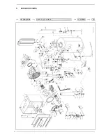
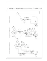
Page 32: ...32 5 EXPLODED VIEWS COD TYPE DATE PAGE 3810009 505 DEWY 30 130 HE FS 31 10 2007 1 6 ...

Page 33: ...COD TYPE DATE PAGE 3810009 505 DEWY 30 130 HE FS 31 10 2007 2 6 33 ...

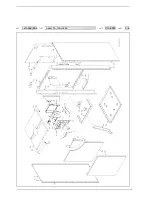
Page 34: ...34 COD TYPE DATE PAGE 3810009 505 DEWY 30 130 HE FS 31 10 2007 3 6 ...

Page 35: ...2030226 Gasket Ø 10 2x14 8x2 35 6017210 Manual air vent 1 4 36 5183720 Rectang expansion vessel 10 l 3 8 M 37 6292901 Sealed chamber supporting bracket 38 6231351 Plunged sensor 39 6022010 Sensor gasket 40 6291900 C H return manifold 41 6291810 C H flow manifold 42 6297400 Tee joint M 1 2 x16 43 6040202 Pressure relief valve 1 2 3 bar 44 6073315 Expansion vessel fixing bracket 45 1010213 Condensat...

Page 36: ...93202 Pipe conn low temp pump mixer valve 180 6146719 50 C safety stat 181 6297100 Grundfos UP 15 14 pump 182 6297300 Pipe conn recircul pump fixing jig 183 6297200 Pipe conn D H W tank recircul pump 184 6120501 Nipple 1 2 x1 2 OT 185 6078603 Non return valve 1 2 186 6017201 Air vent 1 4 187 6149850 Pipe connecting filling to tank 188 5199100 Filling Loop 189 6157627 H W supply tube conn 190 61576...

Page 37: ...78965 O ring ø 223x231x4 112 6278966 Glass fibre sealing cord Ø 6 113 6269004 Combustion chamber door insulation 114 6174808 Gasket for burner flange 115 6278963 Burner fixing screw 116 6278961 Comb chamber rear insul fixing screw 117 6278960 Comb chamber rear insul fixing plate 118 6120511 Nipple 3 4 x3 4 OT 119 6226601 Spring for heat exchanger connection 120 6163102 Gas valve flange c w brass n...

Page 38: ...e kept to a minimum Pipework must be angled down from the boiler with a fall of at least 2 5 The pipework must be supported at a distance of 0 5m for inclined runs and 1 0m for vertical runs Condensate traps Where the condensate drain is not sealed to the discharge connection a trap will be required The water seal should be 38mm or more for external discharge and 75mm or more for internal discharg...

Page 39: ......

Page 40: ...Cod 6255543A 08 10 Documentation Dpt Sime Ltd 1a Blue Ridge Park Thunderhead Ridge Glasshoughton Castleford WF10 4UA Phone 0845 9011114 Fax 0845 9011115 www sime ltd uk Email enquiries sime ltd uk ...

Reviews: