79
IT
ES
ENG
3.2
TEMPERATURE PROBE
AND WATER PRESSURE
TRANSDUCER
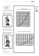
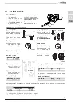
Antifreeze system made up of the NTC hea-
ting sensor that activates when the water
temperature reaches 6°C.
Tables 1 – 1/a
include the resistance values (
Ω
) that are
obtained on the valve when the temperatu-
re changes and those on the
transducer when pressure changes.
The module does not work when the hea-
ting probe (SM) is cut off.
3.3
ELECTRONIC IGNITION
Flame detection ignition is controlled by two
electrodes that guarantee maximum safety
with intervention time, for accidental shut-
downs or no gas, within 1 second.
3.3.1
Operating cycle
Rotate the selector to summer or winter
and check the green led (
) to make sure
power is on. The burner should ignite within
max. 10 seconds. Failed ignition consequen-
tly lighting the appliance block signal may
occur due to the following:
–
Ignition electrode does not spark
Only gas is supplied to the boiler and,
after 10 sec., the block led turns on.
It may be caused by the fact that the elec-
trode is cut-off or is not secured in the
ignition transformer terminal.
–
No flame detection
At ignition, the electrode continues to
spark even though the burner is on. After
10 sec. it stops sparking, the burner
turns off and the block led turns on.
The detection electrode wire is cut-off or
the electrode is grounded; the electrode
is worn and requires replacement. The
electronic board is defective.
A sudden blackout immediately turned off
the burner, when power is restored, the boi-
ler will automatically start.
3.4
AIR PRESSURE
SWITCH
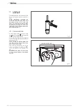
The pressure switch signal value is measu-
red by a specific tool connected to the posi-
tive and negative pressure fixtures.
The pressure switch is factory set to 35-
45 Pa.
3.5
AREA SYSTEM
ELECTRICAL
CONNECTIONS
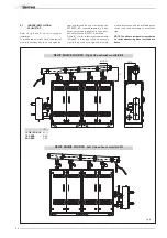
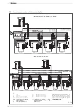
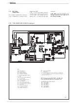
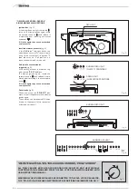
For the
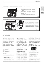
“DEWY EQUIPE 60 BOX/P60
BOX”
heat module use a separate electri-
cal line where the room thermostats with
relevant area valves or pumps must be
connected.
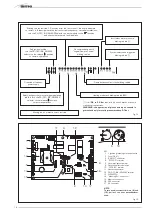
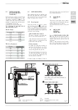
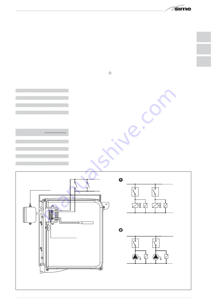
Switch or relay contacts must be connec-
ted to the electronic board connector (J2)
after removing the existent bridge (fig. 17).
CR1
CR
TA
(5)
SONDA
SANITARIO
CONNETTORE J2
COPERTURA
TA
(6)
SB
(11)
SB
(12)
CIRCUITO CON VALVOLE DI ZONA
NOTA: I relé vengono impiegati solo nel caso
le valvole di zona siano prive di micro.
L
N
TA
TA1
VZ
R
VZ1
R1
CIRCUITO CON POMPE DI ZONA
L
N
TA
TA
P
R
P1
R1
Fig. 17
KEY
TA-TA1
Area room thermostat
VZ-VZ1
Area valve
R-R1
Area relay
CR-CR1
Area relay contact or valve switch
P-P1
Area pump
TABLE 1 (Probe)
Temperature (°C)
Resistance (
Ω
)
20
12.090
30
8.313
40
5.828
50
4.161
60
3.021
70
2.229
80
1.669
TABLA 1/a (Transducer)
Pressure
Resistance (
Ω
)
(bar)
min.
max.
0
297
320
0,5
260
269
1
222
228
1,5
195
200
2
167
173
2,5
137
143
3
108
113
3,5
90
94
COVER
CIRCUIT WITH AREA VALVES
CIRCUIT WITH AREA PUMPS
NOTE: Relays are only used when area valves do
not have switches.
J2 CONNECTOR
HOT WATER
PROBE
Summary of Contents for DEWY EQUIPE 120 BOX
Page 2: ......
Page 88: ......
Page 89: ...TAGLIARE LUNGO LA LINEA TRATTEGGIATA ...
Page 90: ......
Page 91: ......

