Installation, use and maintenance manual
MANUAL CODE: 6328407
Page 40 / 148
1.3
Copyright
These instructions contain information protected
by copyright. Do not photocopy, duplicate,
translate or store these usage instructions on
storage media either in whole or in part, without
prior authorisation from the Supplier. Any violations
shall be subject to compensation for damages. All
rights, including those resulting from the issuance of
patents or registration of utility models, are
reserved.
1.4
Operating principle
The appliances in the 1.6 kW range produce
domestic hot water mainly using heat-pump
technology. A heat pump transfers thermal energy
from a source at a lower temperature to a source
at a higher temperature, and vice versa (using
heat exchangers).
The appliance uses a hydraulic circuit composed
of a compressor, an evaporator, a capacitor and
a thermal expansion valve. A refrigerant fluid/gas
flows in the circuit (see section 4.6).
The compressor creates a difference in pressure
inside the circuit, which creates a thermodynamic
cycle. The compressor aspirates the refrigerant
fluid through an evaporator, where it evaporates
at low pressure absorbing heat, compresses it and
forces it towards the capacitor, where the fluid
condenses at high pressure, releasing the
absorbed heat. The fluid then passes through a
capillary tube and, decreasing in pressure and
temperature, starts to vaporise and enters the
evaporator again, restarting the cycle.
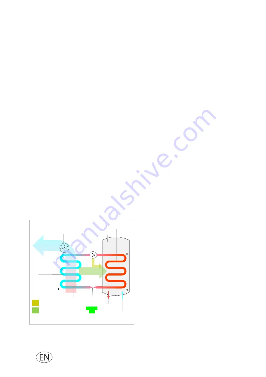
Fig. 5 – Operating principle
The appliance operating
principle is as follows
I-II:
the refrigerant fluid aspirated by the
compressor runs inside the evaporator and, while
evaporating, absorbs the ecological heat
provided by the air.
At the same time, the air in the space is aspirated
by the appliance, thanks to the fan. As it passes on
the finned battery of the evaporator, the air
releases its heat;
II-III:
the refrigerant gas passes inside the
compressor and there is an increase in pressure
which raises the temperature, turning the gas into
overheated vapour;
III-IV:
in the capacitor, the refrigerant gas releases
its heat in the water in the tank (boiler). This
exchange process transforms the refrigerant from
an overheated vapour into a liquid state,
condensing at a constant pressure and dropping
in temperature;
IV-I:
the refrigerant liquid passes through the
capillary tube, quickly dropping both in pressure
and temperature. It partially vaporises, returning to
the initial pressure and temperature conditions. The
thermodynamic cycle can now start again.
Ecological
heat
Capacitor
Air
Evaporator
Fan
Compressor
Capillary
tube
Tank
Cold water
Hot water
Electrical heat
Summary of Contents for ECOMAXI 160 ErP
Page 147: ......

