9
1
2
3
4
5
6
7
8
9
10
11
12
13
14
15
17
16
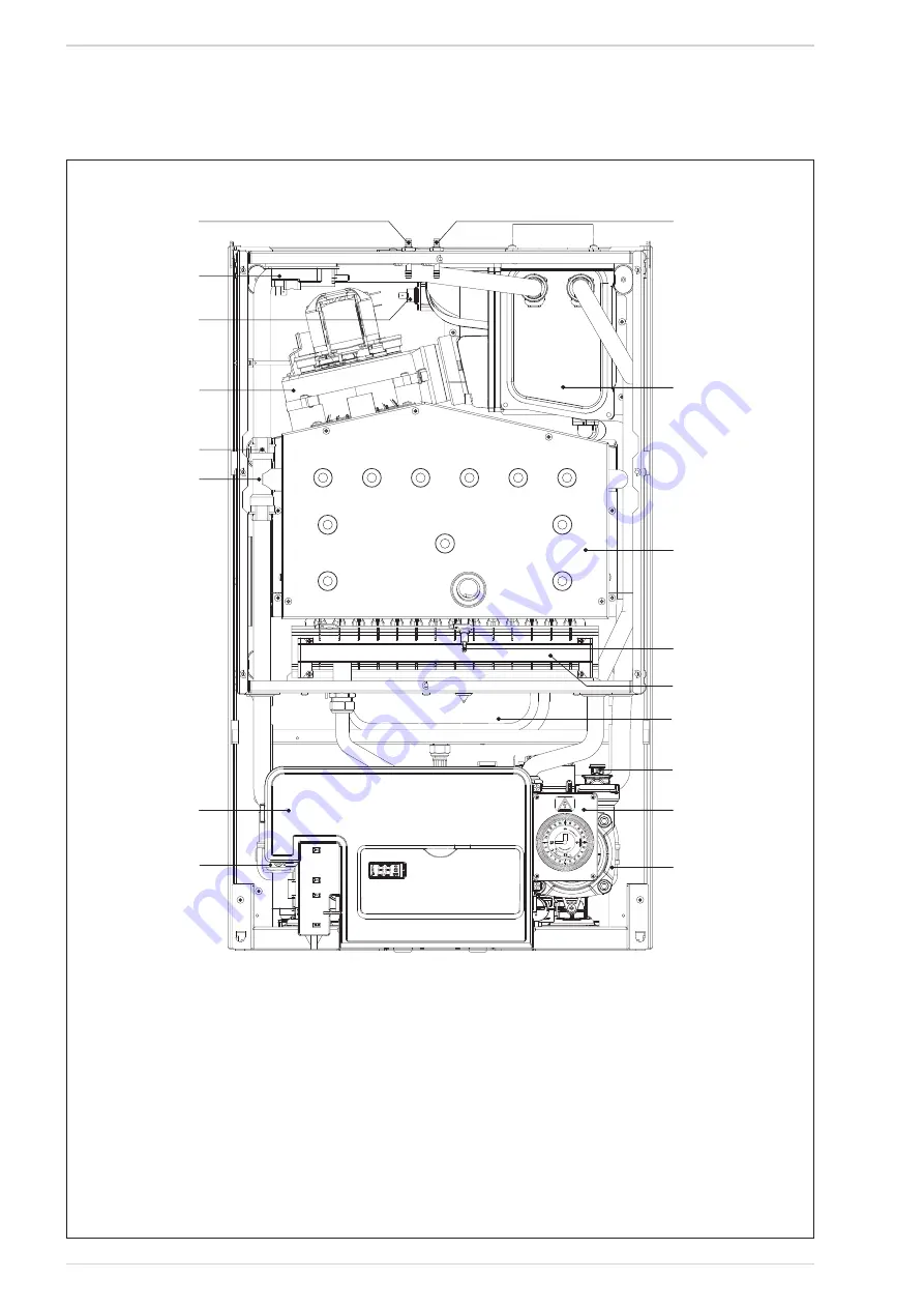
Fig. 3
K
KE
EY
Y
1 Control panel
2 Primary exchanger
3 SM sensor (SM1 and safety stat SM2)
4 Fan
5 Smoke stat 100 °C
6 Air pressure switch
7 Negative test point
8 Positive test point
9 Post-condenser
10 Combustion chamber
11 Ignition/ ionisation electrode
12 Burner
13 Automatic air vent
14 Programming clock (optional)
15 Pump
16 Expansion vessel
17 Condensate trap
1.5
MAIN COMPONENTS (Fig. 3)
NOTE: Analogue pressure gauge see fig. 18/a.


