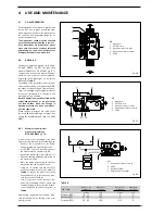
two changes of direction in the duct, the
maximum length must not be greater
than 2 m.
2.9
SEPARATE DUCTS
“25/60 BF -30/60 BF”
In the installation it is best to observe the
directions requested by the Norms and a
few practical considerations:
–With direct external suction, when the
duct is than 1 m in length, insulation is
recommended in order to avoid, in parti-
cularly cold periods, the formation of
dew on the outside of the tubing.
–With discharge duct positioned on the
outside of the building, or in cold environ-
ments, insulation is necessary to avoid
starting failures of the burner. In such
cases, a system for the collection of con-
densation must organised.
– If a segment of the flue passes through
a flammable wall, this segment must be
insulated with a glass wool pipe insula-
tor 30 mm thick, with a density of 50
kg/m
3
.
The maximum total length obtained by
summing up the lengths of the suction and
discharge tubing is determined by the load
losses of the single fittings attached (exclu-
ding the splitter) and must not be greater
than 8.00 mm H
2
0 (vers. “25/60”) and
9.00 mm H
2
O (vers. “30/60”).
For the load
losses of the fittings refer to
Table 2
.
2.9.1
Fittings separate ducts
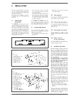
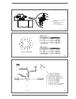
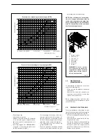
A kit code 8093000 (fig. 14) is supplied for
the realisation of this type of discharge.
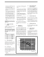
The sector diaphragm that comes with the
kit must be used as indicated in fig. 15
according to the maximum load loss
allowed in both ducts.
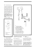
The complete range of the fittings neces-
sary for each type of installation is given in
fig. 16.
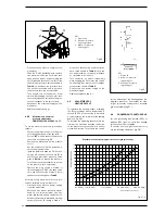
79
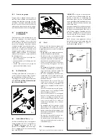
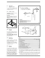
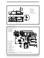
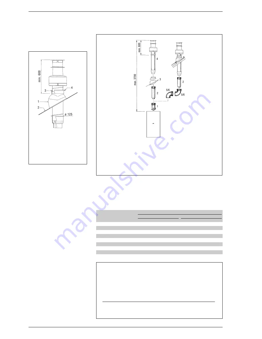
KEY
1
Tile with articulated joint
2
Lead panel
3
Collar
4
Locking screw
Fig. 12
Fig. 13
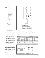
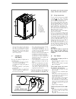
KEY
1
Vertical extension L. 194
with take-off point code 8086903
2
Extension L. 815 code 8084804
3
Tile with articulation joint code 8091300
4
Roof outlet terminal L. 1284 code 8091200
5
Supplementaty 90° elbow code 8085601
Example of allowable installation calculation (
“25/60”
version) in that the sum of the head
losses of the single fittings is less than 8.00 mm H
2
O:
Intake
Outlet
7 meter horizontal pipe ø 80 x 0.20
1.40
–
7 meter vertical pipe ø 80 x 0.30
–2.10
n° 2 90° elbows ø 80 x 0.30
0.60
–
n° 2 90° elbows ø 80 x 0.40
–0.80
N° 1 terminal ø 80
0.10
0.30
Total head loss
2.10
+
3.20
=
5
.
3 mm H2O
With this total head loss, remove the ø 38 baffle from the intake pipe.
TABLE 2
Accessories ø 80
Head loss (mm H
2
O)
“25/60”
version
“30/60”
version
Inlet
Outlet
Roof outlet
Inlet
Outlet
Roof outlet
90° elbow MF
0.30
0.40
–0.30
0.50
–
45° elbow MF
0.20
0.30
–0.20
0.40
–
Extension L. 1000 (horizontal)
0.20
0.30
–0.20
0.40
–
Extension L. 1000 (vertical)
0.30
0.20
–0.30
0.30
–
Outlet terminal
–0.30
–
–0.40
–
Intake terminal
0.10
––0.10
––
Doubler fitting
0.20
––
0.30
––
Roof outlet terminal L. 1390
–– 0.50
––0.60
Tee condensation outlet
–1.00
–
– 1.10
–


