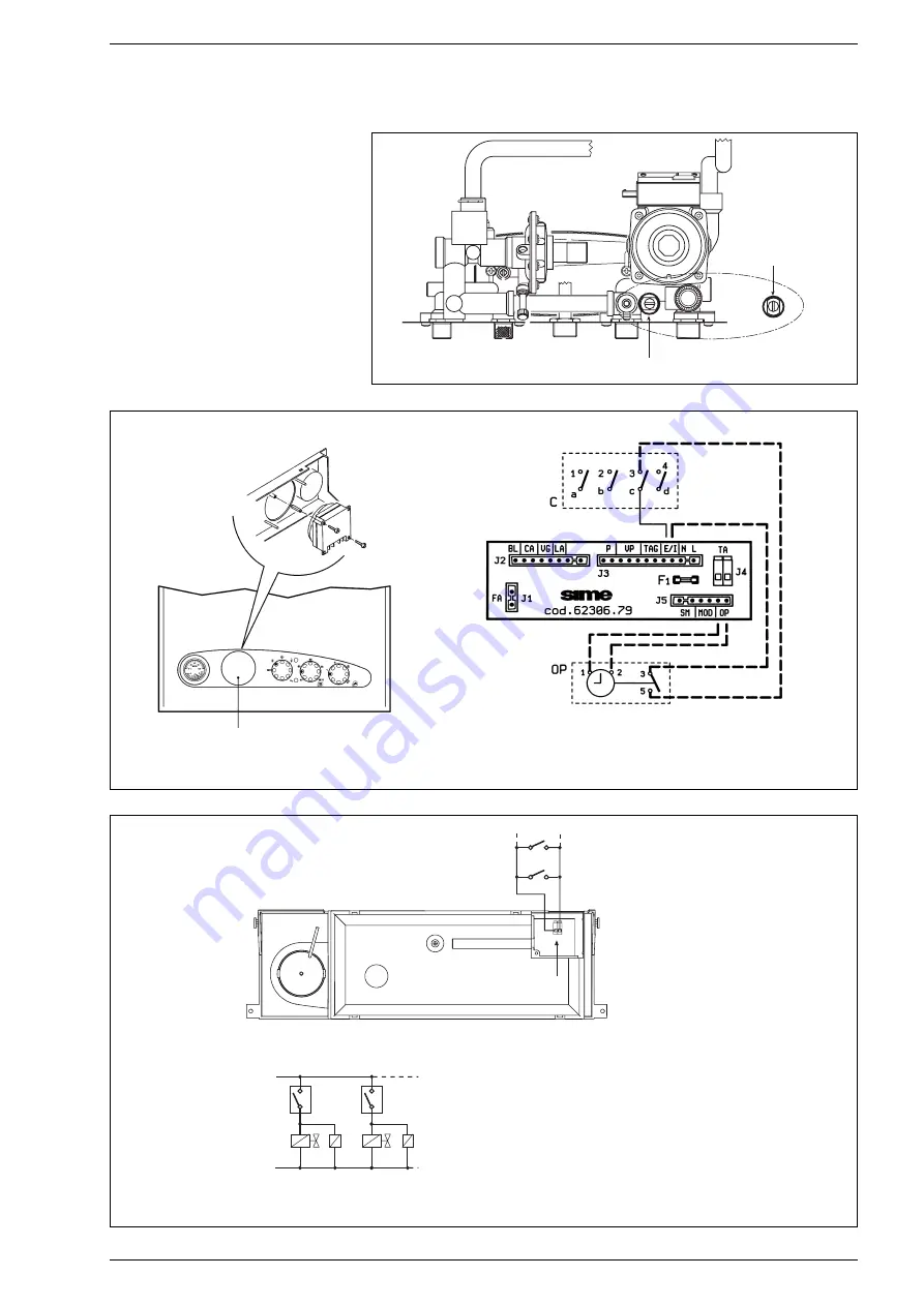
of the rotary switch and connect it to the
terminal 3 of the time-clock.
Connect the unit as shown in the wiring dia-
gram (fig. 25).
3.9
MAINS ELECTRICITY
CONNECTION
Use a separate electricity supply to con-
nect the room stats and relative zone val-
ves.
The micro or relay contact connection is
made to terminals 22-23 (TA) of the cir-
cuit board after having removed the jum-
per (fig. 26).
84
Fig. 25
L
N
TA
TA
1
VZ
R
VZ
1
R
1
NOTA: I relé vengono impiegati solo nel caso
le valvole di zona siano prive di micro.
CR
1
CR
Connettore "TA"
22 23
Fig. 26
By-pass inserito
By-pass escluso
Fig. 24/a
REMOVE
KEY
OP
Time programmer
C
Rotary switch
KEY
TA-TA1
Zone room stat
VZ-VZ1
Zone gas valve
R-R1
Zone relay
CR-CR1 Zone microvalve or relay contact
NOTE: The relays are only used where the
zone valves are not fitted with micros.
“TA” connector
By pass off
By-pass on


