background image

43

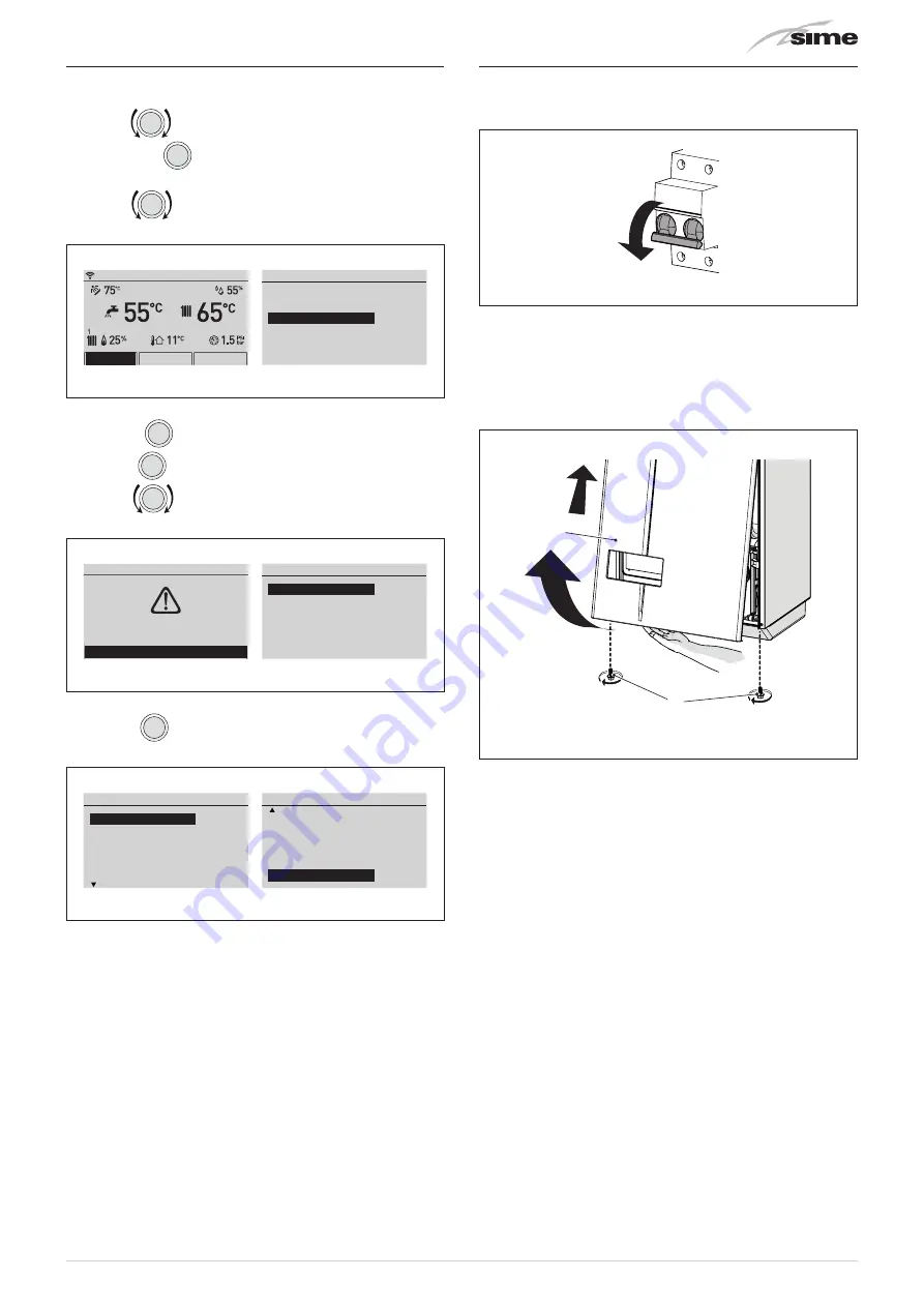
6.16  Displaying the set system solution

From the 

“Main screen”

:

–  turn the 

 encoder to select the 

“Menu”

 (Menu) function 

and press the 

click

 encoder to enter the 

“Menu”

 (Menu) se-

lection screen

–  turn the 

 encoder to select the 

“TECHNICAL”

 (TECHNI-

CAL) menu

Menu

GENERAL SETTINGS

[...]

INFORMATION

[...]

TECHNICAL

[...]

MENU

MODE

ZONES

Mon 01.01.2018

10:30

Fig. 57

–  press the 

click

 encoder and select 

“Confirm”

 (Confirm), 

press the 

click

 encoder to confirm

–  turn the 

 encoder to select the 

“Plant solution”

 (Plant 

solution) item

Confirm request

Confirm operation

Confirm

TECHNICAL

Plant solution

[...]

Technician param.

[...]

Chimney sweeper

[...]

Info

[...]

Fig. 58

–  press the 

click

 encoder to open the 

“Plant solution”

 (Plant 

solution) screen and display the system solution set.

Plant solution

R5S

0

S1

0

S2

0

PT1000

0

ID1

0

ID2

0

Plant solution

Solution type

1

R1

2

R2

3

R3

4

R4S

5

R5S

6

Fig. 59

6.17  Refilling or emptying

Before carrying out the operation described below, make sure 

that the main system switch is set to "OFF".

OFF

Fig. 60

6.17.1  REFILL operations

Remove the front panel:

–  remove the two screws (1), pull the front panel (2) forwards 

and release it from the top by lifting it.

1

2

Fig. 61

Domestic hot water circuit:

–  open the isolation valves of the domestic hot water circuit (if 

present)

–  open one or more than one hot water valve to fill and bleed the 

domestic hot water circuit

–  once bleeding has been completed, close the hot water valves.

Summary of Contents for MURELLE HT 25 GPL

Page 1: ...Fonderie SIME S p A 6330337 02 2019 R1 Cod USER INSTALLATION AND SERVICING INSTRUCTIONS MURELLE HT Condensing wall mounted boiler EN TRANSLATION OF THE ORIGINAL INSTRUCTIONS ...

Page 2: ...2 ...

Page 3: ...t least one of the fol lowing operations must be carried out set the main system switch to OFF close the gas and water valves for the water heating system In order to ensure optimal appliance operations Sime recommends that maintenance and checks are carried out ONCE A YEAR m WARNINGS It is recommended that all operators read this manual carefully in order to use the appliance in a safe and ration...

Page 4: ...s supply Do not modify the safety or adjustment devices without authorization and in structions from the manufacturer d IT IS FORBIDDEN Do not block the condensate drain if present Do not pull detach or twist the electri cal cables coming out of the appliance even if the appliance is disconnected from the mains power supply Do not expose the boiler to atmos pheric agents These boilers can also be ...

Page 5: ...nd year of manufacture SYMBOLS a WARNING To indicate actions which if not carried out correctly can result in injury of a general nature or may damage or cause the appliance to malfunction these actions therefore require particular caution and adequate preparation f ELECTRICAL HAZARD To indicate actions which if not carried out correct ly could lead to injury of an electrical nature these actions ...

Page 6: ...6 ...

Page 7: ...10 1 3 1 Acqua Calda Sanitaria 10 1 3 2 Riscaldamento 10 1 3 3 Funzione vacanze 11 1 4 Segnalazione anomalia 12 1 5 Programmazione oraria 12 2 SPEGNIMENTO 13 2 1 Spegnimento temporaneo 13 2 2 Spegnimento per lunghi periodi 13 3 MANUTENZIONE 14 3 1 Regolamentazioni 14 3 2 Pulizia esterna 14 3 2 1 Pulizia della mantellatura 14 4 SMALTIMENTO 14 4 1 Smaltimento dell apparecchio Direttiva Europea 2012 ...

Page 8: ...ure 5 DHW temperature 6 Date 7 Boiler delivery temperature 8 Room humidity level 9 Time 10 System pressure 11 Measured outdoor temperature 12 Presence of external sensor SE 13 Heating circuit 1 heat request active 14 Heating circuit 2 heat request active 15 Burner active 16 Burner modulation percentage 17 Domestic hot water circuit heat request active 18 Heat pump request in cold mode active 19 He...

Page 9: ...and restore the heating system pressure until the pressure gauge 1 shows a reading of 1 1 2 bar close the filling valve 2 1 2 Fig 2 1 2 2 Ignition After having carried out the preliminary checks perform the following to start the boiler set the main system switch to ON after a few seconds the Main screen is shown ON MENU MODE ZONES Mon 01 01 2018 10 30 Fig 3 turn the encoder to select the Mode Mod...

Page 10: ...der to confirm the highlighted Row and access the modifiable area DHW Function Mode MAN Hot water set 50 C Program Time Fig 9 turn the encoder to modify the Data value in the per mitted field e g MAN AUTO OFF press the click encoder to confirm any modifications made and go back to the row Function mode Function Mode m CAUTION For information on boiler time programming see Time Programming 1 3 2 He...

Page 11: ...To set the holiday function from the Main screen turn the encoder to select the Mode Mode function press the encoder click to confirm one of the function modes Summer Summer or Winter Winter turn the encoder to select the Holiday function Hol iday function Summer Winter Off DHW MAN 40 C Heating AUTO 20 C Holiday function OFF Esc Fig 15 press the encoder click to confirm the Holiday function Holida...

Page 12: ...ammed time band the boiler works in COM FORT heating mode while outside the programmed time band it works in REDUCED heating mode press the encoder click to confirm Program Time Pro gram Time and go into the modifiable area Confirm Heating Time Program 0246 81 01 21 41 61 82 02 22 4 1 06 00 08 00 2 11 00 13 00 3 4 18 00 23 00 MONDAY Day s Fig 21 turn the encoder to select the Single days or the Gr...

Page 13: ...ily for a weekend short trip etc and if the outside temperature is at ZERO set the main system switch to OFF close the gas valve OFF Fig 26 2 2 Shutting down for long periods If the boiler is to be left unused for a long period the following operations need to be carried out switch off the boiler as specified in the Temporary shut down section set the main system switch to OFF OFF Fig 27 close the...

Page 14: ...the cladding When cleaning the cladding use a cloth dampened with soap and water or alcohol for stubborn marks d IT IS FORBIDDEN to use abrasive products 4 DISPOSAL 4 1 Disposal of the equipment European Di rective 2012 19 EU Boilers and electrical and electronic applianc es from private households must not be dis posed of as unsorted municipal waste at the end of their life Instead they must be t...

Page 15: ...che 16 5 2 Dispositivi di controllo e sicurezza 16 5 3 Identificazione 16 5 3 1 Targa tecnica 17 5 4 Struttura 18 5 5 Caratteristiche tecniche 19 5 6 Circuito idraulico di principio 20 5 7 Sonde 20 5 8 Vaso di espansione 21 5 9 Pompa di circolazione 21 5 10 Pannello comandi 22 5 11 Schema elettrico 23 ...

Page 16: ...made the chimney sweep function lasts 15 minutes and makes the job of the qualified technician easier when measuring the pa rameters and combustion efficiency domestic hot water comfort function which allows the time necessary for the hot water to become available to be reduced and ensures that the temperature is stable screen display of the operating and self diagnostic parame ters with error cod...

Page 17: ...OF GAS SUPPLY PRESSURE MIN HEAT INPUT NOx CLASS GAS COUNCIL NUMBER CODE UK WRAS CERTIFICATION UK ELECTRICAL PROTECTION DEGREE N PIN TYPE OF GAS TYPE OF GAS TYPE OF GAS FLOW RATE MAX OPERATING PRESSURE ELECTRICAL SUPPLY MAXIMUM ABSORBED POWER MAX HEAT INPUT COUNTRY OF INTENDED INSTALLTION APPLIANCE CATEGORY D H W CONTENT Fig 29 m CAUTION Tampering with removing or failing to display the identificat...

Page 18: ...e siphon 11 Diverter valve 12 System filling unit 13 Domestic hot water sensor 14 Control panel 15 Domestic hot water heat exchanger 16 Gas valve 17 Tap fittings cover 18 Domestic hot water filter 19 System relief valve 20 Boiler drain 21 System pump 22 Water pressure transducer 23 Automatic bleed valve 24 Fan 25 Air gas mixer 26 Expansion vessel 27 Air inlet pipe 28 Air smoke chamber 29 Smoke flu...

Page 19: ... H W flow rate ΔT 30 C EN 13203 l min 11 4 14 0 16 1 Continuous D H W flow rate ΔT 25 C ΔT 35 C l min 13 9 9 7 17 9 12 6 19 4 13 8 Minimum D H W flow rate l min 2 2 2 Max PMW Min Pressure bar 7 0 5 7 0 5 7 0 5 kPa 700 50 700 50 700 50 ENERGY PERFORMANCE HEATING Heating seasonal energy efficiency class A A A Heating seasonal energy efficiency 93 93 93 Sound power dB A 55 57 57 DOMESTIC HOT WATER Do...

Page 20: ...ery sensor 7 Domestic hot water heat exchanger 8 Pressure transducer 9 Automatic bleed valve 10 Pump 11 System expansion vessel 12 Diverter valve 13 Automatic by pass 14 Domestic hot water sensor 15 Gas valve 16 Domestic hot water flow meter 17 Domestic hot water filter 18 Boiler drain 19 System relief valve 20 System filling 21 Condensate siphon outlet 5 7 Sensors The sensors installed have the f...

Page 21: ...sion vessel must be prearranged The difference in height between the relief valve and the highest point of the system cannot exceed 6 metres If the difference is greater than 6 metres increase the prefilling pressure of the expansion vessel and the system when cold by 0 1 bar for each meter increase 5 9 Circulation pump The flow head performance curve available for the heating sys tem is shown in ...

Page 22: ...perature 6 Date 7 Boiler delivery temperature 8 Room humidity level 9 Time 10 System pressure 11 Measured outdoor temperature 12 Presence of external sensor SE 13 Heating circuit 1 heat request active 14 Heating circuit 2 heat request active 15 Burner active 16 Burner modulation percentage 17 Domestic hot water circuit heat request active 18 Heat pump request in cold mode active 19 Heat pump activ...

Page 23: ...9 8 7 10 11 12 13 14 15 16 17 18 R1 R2 R3 WIFI YELLOW ORANGE RED WHITE GREEN RE1 S2 AUX S1 AUX S1 PT1000 L Line N Neutral TRA Ignition transformer RE1 Resistance PM Modulating pump V Fan EAR Ignition Detection electrode EV Gas solenoid valve SE External sensor SS Domestic hot water sensor SM Delivery sensor SR Return sensor SR TS Safety thermostat TFU Thermal fuse SF Smoke flue gas probe FLM Flow ...

Page 24: ...L Live N Neutral Ensure that the special power cable is only replaced with a cable ordered as a spare part and connected by professionally qualified personnel m CAUTION Users must Connect the earth wire to an effective earthing sys tem The manufacturer is not responsible for any damage caused by failure to earth the appliance or failure to observe the information provided in the wiring diagrams d ...

Page 25: ...RIEMPIMENTO 43 6 17 2 Operazioni di SVUOTAMENTO 44 7 MESSA IN SERVIZIO 45 7 1 Operazioni preliminari 45 7 2 Prima messa in funzione 45 7 3 Visualizzazioni e impostazioni dal Pannello Comandi 45 7 3 1 Impostazioni da funzione MODO 45 7 3 2 Segnalazione anomalia 47 7 3 3 Programmazione oraria 47 7 3 4 Navigazione da funzione MODO 48 7 3 5 Impostazioni da funzione MENU 49 7 3 6 Navigazione da funzion...

Page 26: ...g with expansion plugs d IT IS FORBIDDEN Do not leave packaging material around or near chil dren since it could be dangerous Dispose of it as pre scribed by legislation in force 6 2 Dimensions and weight H W D Fig 36 Description MURELLE HT 25 30 35 W mm 450 450 450 D mm 315 315 315 H mm 800 800 800 Weight kg 32 4 34 0 35 6 6 3 Handling Once the packaging has been removed the appliance is to be ha...

Page 27: ...ssel ensures total absorption of the fluid di lation in the system the pump flow head performance is sufficient for the system characteristics the system is clean free of any sludge deposits de aerated and air tight For system cleaning please refer to the relevant paragraph m CAUTION The manufacturer declines all liability for any damage caused by an incorrect implementation of the smoke outlet or...

Page 28: ...3 Fig 39 m CAUTION The height of the boiler is to be such that disassembly and maintenance interventions are facilitated 6 9 Plumbing connections The plumbing connections have the following characteristics and dimensions 65 65 65 65 48 450 M Sc U G E R 155 115 Sc Fig 40 Description MURELLE HT 25 30 35 M System delivery Ø 3 4 G R System return Ø 3 4 G U Domestic hot water output Ø 1 2 G E Domestic ...

Page 29: ...et pipe prepared above 1 2 3 Fig 41 6 12 Gas supply MURELLE HT boilers leave the factory specifically prearranged for G20 gas or G31 The G20 models can be converted to function with G31 using the specific nozzle kit optional provided by Sime on request separately from the boiler If changing the type of gas to be used carry out the entire GAS CONVERSION phase of the appliance Boiler connection to t...

Page 30: ...33 Concentric roof smoke outlet The pipes can start from the boiler but the outlets must be concentric or close together no more than 50 cm to be subject to similar wind conditions C43 Outlet and inlet in shared or separate flue pipes but subjected to similar wind conditions C53 Separate wall or roof inlet and outlet in different pres sure areas NOTE the inlet and outlet must never be positioned o...

Page 31: ... the SEPARATE DUCTS KIT product code 8089912 for Ø 80 mm or product code 8089913 for Ø 60 mm The accessories must be ordered sepa rately from the boiler and connected to the other accessories chosen from those listed in the table below Accessory 8089912 for Ø 80 mm is supplied with an INLET DIA PHRAGM NOT TO BE USED Accessory 8089913 for Ø 60 mm is supplied with an inlet collar which must be repla...

Page 32: ...10 Roof outlet terminal 8091204 0 80 0 10 1 10 0 15 Description Code Load loss mm H2O MURELLE HT 35 Inlet Outlet Separate duct kit 8089912 90 curve MF 8077450 0 30 0 40 45 curve MF 8077451 0 25 0 25 Horizontal extension W 1000 mm 8077351 0 25 0 25 Vertical extension W 1000 mm 8077351 0 25 0 25 Wall terminal 8089501 0 15 0 50 Wall coaxial outlet 8091210 Roof outlet terminal 8091204 1 5 0 2 Load los...

Page 33: ...ses 3 95 mmH2O of the required accessories is less than 15 0 mmH2O and the total extension for each single duct is still less than 25 m 6 14 Electrical connections The boiler is equipped with a ready wired power cable which is to be connected to a 230V 50 Hz network If this cable needs to be replaced an original spare must be re quested from Sime Therefore only the connections of the original comp...

Page 34: ...d connected by a professionally qualified person to connect the earth wire to an effective earthing system that before any intervention on the boiler the mains power is disconnected by setting the main system switch to OFF The manufacturer is not responsible for any damage caused by failure to earth the appliance or failure to ob serve the information provided in the wiring diagrams d IT IS FORBID...

Page 35: ... encoder to confirm any modifications made and go back to the Ext probe modul Ext probe modul row Circuit 1 Function Mode ON Flow Temp max set 20 C Flow Temp min set 17 C Ext probe modul YES Weather comp curve 1 0 Weather comp Offset 0 C Fig 55 Repeat to set the desired Climatic curve and Climatic curve offset 6 14 2 Chrono thermostat or Air Thermostat The electrical connection of the chrono therm...

Page 36: ...ne direct multi zone circuit a remote solar hot water tank for preheating domestic hot water and a hot cold mode system To set parameter TSP 02 follow the procedure described in the section Parameter setting and display m CAUTION In relation to the value set under parameter TSP 02 the following parameters take on the values shown in the table CHOOSEN HYDRUALIC SETUP 1 2 3 5 6 8 9 10 12 14 15 TSP D...

Page 37: ...rcuit pump 2 TZ1 2 Zone ambient thermostat SP Hydraulic separator Solution 2 System a mixed multi zone circuit R M SE PC1 Ts1 VMIX1 Sm1 U ACS R1 SE R2 S1AUX S1PT1000 R3 TZ1 TA1 SP R1 PC1 R2 VMIX1 AP R3 VMIX1 CH S1PT1000 Ts1 S1 AUX Sm1 TA1 TZ1 SE SE M Boiler delivery U Domestic hot water output R Boiler return DHW Domestic hot water SE External sensor PC1 Circuit pump 1 VMIX1 Mixer valve circuit 1 ...

Page 38: ... safety thermostat TZ1 2 Zone thermostat SP Hydraulic separator Solution 5 System with a mixed multi zone circuit and a remote hot water tank for preheating domestic hot water R M SE U E ACS R1 SE R2 S1AUX S1PT1000 R3 SPS S2AUX PC1 Ts1 VMIX1 Sm1 TZ1 SP TA1 S1PT1000 Ts1 S1 AUX Sm1 R1 PC1 R2 VMIX1 AP R3 VMIX1 AC TA1 TZ1 SE SE S2 AUX SPS M Boiler delivery U Domestic hot water output E Domestic hot wa...

Page 39: ...omestic hot water preheating sensor SP Hydraulic separator Solution 8 System with one direct multi zone circuit and a remote solar hot water tank for preheating domestic hot water SPS SBS PS SC R E M U SE ACS S1AUX SE S2AUX SP PC1 R2 S1PT1000 TZ1 TA1 R1 R1 PC1 R2 PS TA1 TZ1 S1PT1000 SC SE SE S1 AUX SBS S2 AUX SPS M Boiler delivery U Domestic hot water output E Domestic hot water inlet R Boiler ret...

Page 40: ...ar manifold probe PS Solar pump SP Hydraulic separator Solution 10 System with instant boiler with one direct multi zone circuit a mixed multi zone circuit and a remote solar hot water tank for preheating domestic hot water PS SC SBS R M SE U E S2 AUX TA2 SP PC2 TZ2 PC1 Ts1 VMIX1 Sm1 TZ1 R1 R2 S1AUX ID1 R3 TA1 R5 SE ACS R4 S1PT1000 R1 PC1 R2 VMIX1 AP R3 VMIX1 CH R4 PS R5 PC2 TA1 TZ1 TA2 TZ2 S1PT10...

Page 41: ...t Syst Systems Solution 14 System with one mixed multi zone circuit a fan coil and a hot cold mode system R M U SE ACS ON OFF Fancoil ID2 S1PT1000 TA2 SE TA1 S2AUX S1AUX ID1 R1 R4 R5 R2 R3 Sm1 Ts1 PC1 fancoil MI MC RC RI R M R M PdC V1 MPC RPC PC2 Ts2 VMIX2 Sm2 TZ1 E I R1 PdC R2 VMIX2 AP R3 VMIX2 AC R4 PC1 R5 PC2 TA1 TZ1 TA2 TZ2 S1PT1000 Ts2 SE SE ID1 PdC ID2 Ts1 S1 AUX Sm2 S2 AUX Sm1 TZ2 M Boiler...

Page 42: ...D2 Ts1 TA1 TZ1 S1 AUX SBS S2 AUX Sm1 TZ1 M Boiler delivery U Domestic hot water output E Domestic hot water inlet R Boiler return DHW Domestic hot water SE External sensor OV Thermostatic diverter mixer PC1 Direct circuit pump 1 PdC Heat pump MI System delivery MC Boiler delivery RI System return RC Boiler return MPC Heat pump delivery RPC Heat pump return V1 Check valve PS Solar pump SBS Solar ho...

Page 43: ...nfo Fig 58 press the click encoder to open the Plant solution Plant solution screen and display the system solution set Plant solution R5S 0 S1 0 S2 0 PT1000 0 ID1 0 ID2 0 Plant solution Solution type 1 R1 2 R2 3 R3 4 R4S 5 R5S 6 Fig 59 6 17 Refilling or emptying Before carrying out the operation described below make sure that the main system switch is set to OFF OFF Fig 60 6 17 1 REFILL operation...

Page 44: ... pressure gauge 5 and if necessary top up until the correct pressure reading appears close the automatic bleed valve 3 fill the siphon disconnecting it from the pipe or using by means of the smoke take off point Refit the front panel of the boiler hooking it on at the top push ing it forwards and securing it with the screw 1 which was re moved previously 6 17 2 EMPTYING operations Domestic hot wat...

Page 45: ...nction mode Turn the encoder to select the pre ferred mode e g Winter Winter Summer Winter Off DHW MAN 40 C Heating AUTO 20 C Holiday function OFF Esc Fig 65 adjust the air thermostat and check that the boiler starts and operates correctly 7 3 Main control panel display and settings m CAUTION We recommend not changing the factory settings so as not to alter optimal appliance operation For any spec...

Page 46: ...click encoder to confirm the selected submenu and access the relevant data display Regulation room 1 Function Mode AUTO Set AUTO comfort 20 5 C Set AUTO reduced 17 0 C Set MAN 19 2 C Program Time Room probe run Sì Room probe modul Sì Ext probe modul Sì Weather comp curve 3 0 Regulation room 1 Weather comp curve 3 0 Weather comp Offset 0 C Request limit 0 1 C System inertia 10 Flow Temp max set 60 ...

Page 47: ... the boiler works in COM FORT heating mode while outside the programmed time band it works in REDUCED heating mode press the encoder click to confirm Program Time Pro gram Time and go into the modifiable area Confirm Heating Time Program 0246 81 01 21 41 61 82 02 22 4 1 06 00 08 00 2 11 00 13 00 3 4 18 00 23 00 MONDAY Day s Fig 77 turn the encoder to select the Single days or the Group of days pre...

Page 48: ...Confirm Holiday Schedule Hot water OFF Heat Off Nofrost active Start End Enable holiday NO 02 20 01 01 2018 2018 15 00 15 00 DAY MONTH YEAR HOUR Confirm Summer Winter Off DHW MAN 50 C Holiday function OFF Esc Summer Winter Off DHW MAN 50 C Holiday function OFF Esc Summer Winter Off Acqua calda MAN 50 C Holiday function OFF Esc Summer Winter Off DHW MAN 50 C Heating AUTO 20 C Holiday function OFF E...

Page 49: ... the click encoder to confirm the highlighted submenu and select the modifiable area GENERAL SETTINGS Language ITA Date and time Display Factory settings Fig 85 turn the encoder and modify the data value in the field allowed e g from ENG to ITA GENERAL SETTINGS Language EN Date and time Display Factory settings Fig 86 press the click encoder to confirm the modification and go back to the submenu G...

Page 50: ...ck encoder to go back to the initial submenu Date and time NOTE The user must work in a CIRCULAR manner meaning AL WAYS MOVING FORWARDS even if a mistake is made turn the encoder to select another Menu e g Dis play Display The Display menu allows the user to adjust display contrast duration of the display back lighting The operating procedure is as has been described so far GENERAL SETTINGS Langua...

Page 51: ...re 25 C Return temperature 49 C Exhaust temp 41 C Fig 97 select Back BacK and press the click encoder to return to the submenus turn the encoder to select another submenu Information Boiler Hot Water SCP version 1 00 MB version 0 BC version 0 Fig 98 press the click encoder to confirm the selected submenu and access the relevant data display continue in this way until all the necessary information ...

Page 52: ...eeper Info Fig 103 turn the encoder to select the desired submenu e g Plant solution Plant solution press the click encoder to confirm the selected submenu and enter the modifiable data area Plant solution R5S 0 S1 0 S2 0 PT1000 0 ID1 0 ID2 0 Plant solution Solution type 1 R1 2 R2 3 R3 4 R4S 5 R5S 6 Fig 104 press the click encoder to confirm the highlighted Row and access the modifiable area Plant...

Page 53: ...ay Factory settings Date and time Date Hour 01 20 Gen 11 2018 DAY Hour MONTH MINUTE YEAR Confirm Confirm request Confirm operation Confirm Information Boiler Hot Water SCP version 1 00 MB version 0 BC version 0 Boiler CH Set 40 C CH temperature 25 C Return temperature 49 C Exhaust temp 41 C Hot Water Hot water set 50 C Hot water temp 31 C Flow rate 0 0l min Information Boiler Hot Water SCP version...

Page 54: ...er temp 31 C Temp probe 1 C Temp probe 2 C Temp probe PT1000 C TECHNICAL Plant solution Technician param Chimney sweeper Info TSP parameters Parameter Index 1 1 49 Parameter Value 1 TECHNICAL Plant solution Technician param Chimney sweeper Info TECHNICAL Plant solution Technician param Chimney sweeper Info Chimney sweeper En Chimney Sweeper OFF Power output Confirm request Confirm operation Confir...

Page 55: ... to the main screen 7 3 7 7 REGULATION menu From the Main screen MENU MODE ZONES Mon 01 01 2018 10 30 Fig 113 turn the encoder to select the Zone Zones function press the click encoder to go to the screen to select the Zone Zones Zones Zone 1 Zone 2 Zone 3 Zone 4 Fig 114 turn the encoder to select the desired zone e g Zone 1 Zone 1 press the click encoder to confirm the highlighted zone and go to ...

Page 56: ...one 3 Zone 4 Fig 119 turn the encoder to select the desired zone e g Zone 1 Zone 1 press the click encoder to confirm the highlighted zone and go to the row turn the encoder to select the Configuration Config menu Zone 1 Information Regulation Config Fig 120 press the click encoder to confirm the selected submenu and access the relevant data display Config room 1 Room probe Water circuit Fig 121 t...

Page 57: ...nstallation or configuration error Water circuit parameters hydraulic Parameter Description Type OFF Zone and circuit not present or not controlled CALD Circuits integrated in the boiler fixed Circuit 1 for Zone 1 and Circuit 2 for Zone 2 ATT Circuits managed by actuator on bus M3 M3 ad dress 0 3 Default 0 Address for device connected to bus M3 actuator M3 holding the output relay whether single o...

Page 58: ...be modul YES Ext probe modul YES Weather comp curve 3 0 Weather comp Offset 0 C Request limit 0 1 C System inertia 10 Flow Temp max set 60 C Flow Temp min set 20 C Room antifreeze enable YES Room antifreeze temperature 5 0 C Room sensor adjust 0 0 C Config room 1 Room probe Water circuit Config room 1 Room probe Water circuit Room probe room 1 Type OT Address M3 0 Input 0 Status Water circuit Room...

Page 59: ... press the click encoder to enter the boiler Parameter settings area TECHNICAL Plant solution Technician param Chimney sweeper Info TSP parameters Parameter Index 1 1 49 Parameter Value 1 Fig 128 where the Parameter index Parameter Index refers to the table found in section List of parameters Turn the encoder to scroll through the list of parame ters and check the value If the value of the selecte...

Page 60: ...2 80 C 1 80 14 Zone 1 heating climatic curve K 3 40 C 1 20 15 Minimum Heating Temperature Adjustment Zone 2 20 PAR 16 C 1 20 16 Maximum Heating Temperature Adjustment Zone 2 PAR 15 80 C 1 80 17 Zone 2 heating climatic curve K 3 40 C 1 20 18 Heating Curve Incline 0 80 TSP x 10 2 secs 1 20 19 Heating maximum Output user 0 100 1 100 20 Minimum power heating domestic hot water premixed 0 100 1 0 21 He...

Page 61: ...e pellet boiler 14 supplementary source fireplace or heat pump with photovoltaic consent 15 semi automatic filling 16 DHW recirculation pump 0 33 Relay 4 function 0 not used 1 solar pump 2 direct zone 1 3 N O boiler ON OFF status output 4 N C boiler ON OFF status output 5 N O alarm output 6 N C alarm output 7 direct zone 2 8 mix valve position A 9 mix valve position B 10 not used 11 mix zone pump ...

Page 62: ...ammable timer 5 CH programmable timer 6 alternative source readiness fireplace only 7 system safety thermostat TSI for low temper atures 0 40 Configuring digital input 2 0 not used 1 remote ignition 2 external event boiler off positive pol 3 external event boiler off negative pol 4 DHW programmable timer 5 CH programmable timer 6 alternative source readiness fireplace only 7 system safety thermost...

Page 63: ...onfigured Type No Description ALL 30 Return sensor fault boiler sensor fault for T models ALL 31 PT1000 sensor fault ALL 32 Auxiliary sensor 2 fault ALL 37 Fault due to low network voltage ALL 40 Incorrect network frequency detected ALL 41 Flame loss more than 6 consecutive times ALL 43 Open Therm communication fault ALL 46 Mix zone thermostat intervention fault ALL 47 Mix zone sensor fault ALL 48...

Page 64: ...been removed remove the two screws 1 pull the front panel 2 forwards and release it from the top by lifting it 1 2 Fig 134 use the tabs 3 to release the control panel 4 bring the panel forwards and downwards until it is horizontal 4 3 3 Fig 135 close the gas valve loosen the screw of the mains pressure point 5 and con nect a pressure gauge 5 7 6 Fig 136 open the gas valve power the boiler by setti...

Page 65: ...OFF Power output Chimney sweeper En Chimney Sweeper Low Power output Fig 140 measure the CO2 and check that it corresponds to the value in the table If it does not correspond adjust the minimum power adjustment screw 7 on the gas valve until you obtain the CO2 value shown in the table CO2 values MURELLE HT CO2 G20 CO2 G31 Qmax 0 2 Qmin 0 2 Qmax 0 2 Qmin 0 2 25 9 3 8 8 10 0 10 0 30 9 0 9 0 10 0 10 ...

Page 66: ...zzle heads avoids them being inverted during assembly refit the plate 6 and cover 4 following the above instructions in reverse order carry out the Checks and adjustments then refit the front panel 2 fixing it in place using the two screws 1 1 2 Fig 144 m CAUTION Conversion may ONLY be carried out by Professionally Qualified Personnel m CAUTION If the gas supply is changed from G20 to G31 mark the...

Page 67: ...ut any interventions described set the main system switch to OFF close the gas valve make sure that no hot parts inside the appliance are touched OFF Fig 145 8 2 External cleaning 8 2 1 Cleaning the cladding When cleaning the cladding use a cloth dampened with soap and water or alcohol for stubborn marks d IT IS FORBIDDEN to use abrasive products 8 3 Cleaning the inside of the appliance 8 3 1 Remo...

Page 68: ...n chamber and the burner remove any carbon residue check that the seal and the insulation of the door 12 to the combustion chamber are integral Replace if necessary refit the assembly by carrying out the same operations for re moval but in the reverse order and tighten the screws 11 of the door to the combustion chamber reconnect the connections to the fan and the electrode 8 4 Checks 8 4 1 Checki...

Page 69: ...y of the gas valve and the card Type No Fault Solution ALL 09 No water circulat ing in the system Check the rotation of the pump rotor Check the electrical connec tions Replace the pump ALL 10 Auxiliary sensor 1 fault Check PAR 02 hydraulic configuration Check the electrical con nection ALL 12 Domestic hot water sensor fault in tank mode Set the parameter PAR 04 Combustion configuration to 0 ALL 1...

Page 70: ...tact the Technical Assis tance Centre ALL 100 Communication error with BMU Contact the Technical Assis tance Centre Type No Fault Solution ALL 101 Configuration error with Zone 1 Check the Zone 1 settings in the ZONE menu ALL 102 Configuration error with Zone 2 Check the Zone 2 settings in the ZONE menu ALL 103 Configuration error with Zone 3 Check the Zone 3 settings in the ZONE menu ALL 104 Conf...

Page 71: ... seasonal energy efficiency D HW energy efficiency Sound power dB A 25 XL 24 40 18 93 82 55 30 XL 29 48 18 93 82 57 35 XL 34 56 18 93 81 57 Conforming to Annex IV item 2 of the Delegated Regulations EU No 811 2013 which supplements Directive 2010 30 EU Specific precautionary measures to be adopted at the time of assembly installation or maintenance of the equipment are contained in the boiler inst...

Page 72: ...emperature regime b P1 8 0 kW At 30 of nominal heat output and low temperature regime η1 97 7 Auxiliary electricity consumption Other items At full load elmax 0 044 kW Standby heat loss Pstby 0 095 kW At part load elmin 0 016 kW Ignition burner power consumption Pign 0 kW In standby mode PSB 0 005 kW emissions of nitrogen oxides Выбросы NOx NOx 34 mg kWh For combination heaters Declared load profi...

Page 73: ...ure regime b P1 9 6 kW At 30 of nominal heat output and low temperature regime η1 97 7 Auxiliary electricity consumption Other items At full load elmax 0 054 kW Standby heat loss Pstby 0 101 kW At part load elmin 0 018 kW Ignition burner power consumption Pign 0 kW In standby mode PSB 0 005 kW emissions of nitrogen oxides Выбросы NOx NOx 41 mg kWh For combination heaters Declared load profile Xl W...

Page 74: ...re regime b P1 11 2 kW At 30 of nominal heat output and low temperature regime η1 97 7 Auxiliary electricity consumption Other items At full load elmax 0 060 kW Standby heat loss Pstby 0 113 kW At part load elmin 0 019 kW Ignition burner power consumption Pign 0 kW In standby mode PSB 0 005 kW emissions of nitrogen oxides Выбросы NOx NOx 41 mg kWh For combination heaters Declared load profile Xl W...

Page 75: ...75 ...

Page 76: ...045 Legnago Vr Tel 39 0442 631111 Fax 39 0442 631292 www sime it Fonderie SIME S p A reserves the right to make changes at any time without prior notice in order to improve its products without compromising the essential characteristics ...

Reviews: