User manual for universal counter with batching function SLIK-73
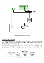
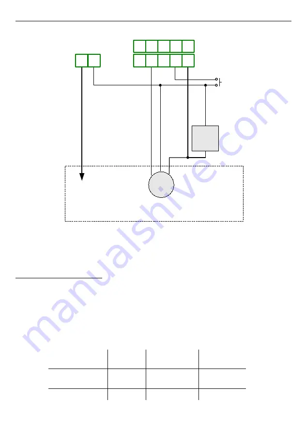
Figure 6.3.
Proposed circuit diagram
6.3.
THE DIGITAL FILTER
To enable the connection of the simple switches as detectors, special digital filter has
been build into the device. This filter allows the counter to proper counting pulses regardless of
the vibration of the contacts of the switches.
The condition of proper counting is providing of time periods of the pulses. The filter can
be set to blocking frequencies higher than 10, 20, 30, 40, 50 ,60 ,70, 80 and 90Hz. The time
periods of stable states "0" (t
0
) and "1" (t
1
) of pulses must be not shorter than 1/2F, where F
the filtered frequency in Hz. See the table below (Tab. 6.2) to check proper periods for all
frequencies.
filter setting (F)
t
0
, t
1
input signal
frequency
input type
OFF
50,0
µ
s /
100,0
µ
s
10 kHz /
5 kHz
electronic
input
10
50,0 ms
10 Hz
17
COM
+
-
16 17 18 19 20
START
pouring
Supply
24V DC
B
D
Controlled system
B
+
Main
valve
Flow
detector
3 4
6 7 8 9 10
R1
-


