background image

User manual - COUNTER   SLIK-94 

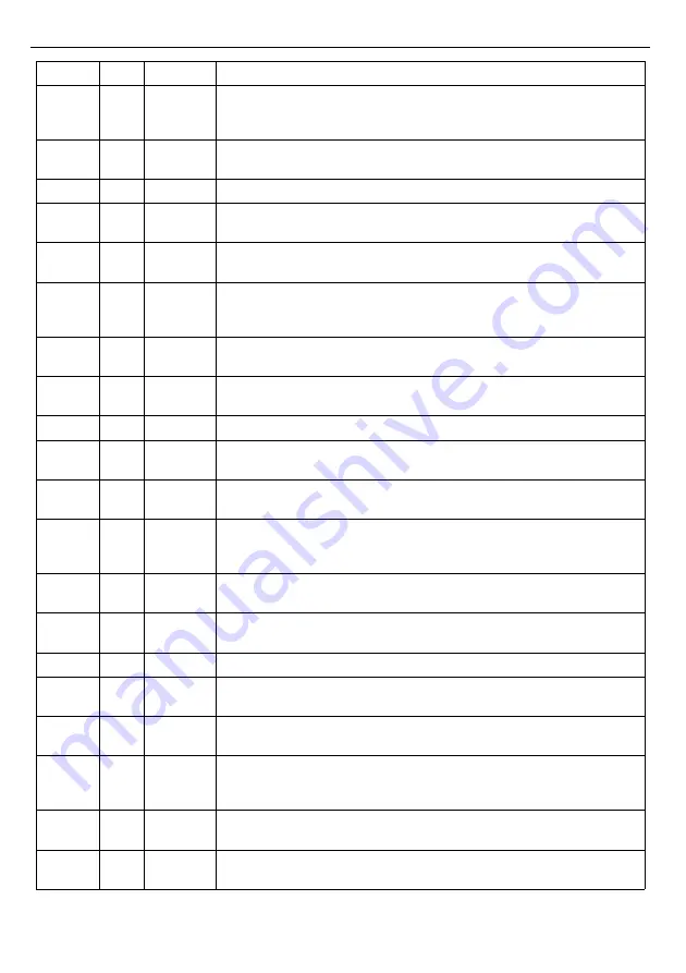
Register Write

Range

Register description

33h

Yes

0÷999

“timE 1”

 parameter in 

“rELAy 1”

 menu (

the time period  of the relay 

active state

), expressed in tenth of seconds or tenth of minutes 

(depending on 

“unit”

 parameter); 

34h

Yes

0 ÷ 1

“unit 1”

 parameter in 

“rELAy 1” 

menu:

0

 - “

SEC

” option; 

1

 - “

min

” option

38h

6

Yes

see descr.

“SEtP 2” 

parameter in 

“rELAy 2”

 menu (high word).

39h

6

Yes

see descr.

“SEtP 2” 

parameter in 

“rELAy 2”

 menu (low word).

Cumulative value of registers 38h and 39h: from -99999 to 999999

3Ah

Yes

0÷3

modE 2

” parameter in  “

rELAy 2

” menu:

0

 - “

noAct

” mode; 

1

 - “

on

” mode; 

2

 - “

oFF

” mode; 

3

 - “

modbuS

” mode

3Bh

Yes

0÷999

“timE 2”

 parameter in 

“rELAy 2”

 menu (

the time period  of the relay 

active state

), expressed in tenth of seconds or tenth of minutes 

(depending on 

“unit”

 parameter); 

3Ch

Yes

0 ÷ 1

“unit 2”

 parameter in 

“rELAy 2” 

menu:

0

 - “

SEC

” option; 

1

 - “

min

” option

3Dh

Yes

0 ÷ 1

rEF  2"


parameter in 

“rELAy 2” 

menu:

0

 - 

"Std"

 option; 

1

 - 

"rELPr1" 

option

40h

6

Yes

see descr.

“SEtP 3” 

parameter in 

“rELAy 3”

 menu (high word).

41h

6

Yes

see descr.

“SEtP 3” 

parameter in 

“rELAy 3”

 menu (low word).

Cumulative value of registers 40h and 41h: from -99999 to 999999

42h

Yes

0÷3

modE 3

” parameter in  “

rELAy 3

” menu:

0

 - “

noAct

” mode; 

1

 - “

on

” mode; 

2

 - “

oFF

” mode; 

3

 - “

modbuS

” mode

43h

Yes

0÷999

“timE 3”

 parameter in 

“rELAy 3”

 menu (

the time period  of the relay 

active state

), expressed in tenth of seconds or tenth of minutes 

(depending on 

“unit”

 parameter); 

44h

Yes

0 ÷ 1

“unit 3”

 parameter in 

“rELAy 3” 

menu:

0

 - “

SEC

” option; 

1

 - “

min

” option

45h

Yes

0 ÷ 1

rEF  3"


parameter in 

“rELAy 3” 

menu:

0

 - 

"Std"

 option; 

1

 - 

"rELPr1" 

option

48h

6

Yes

see descr.

“SEtP 4” 

parameter in 

“rELAy 4”

 menu (high word).

49h

6

Yes

see descr.

“SEtP 4” 

parameter in 

“rELAy 4”

 menu (low word).

Cumulative value of registers 48h and 49h: from -99999 to 999999

4Ah

Yes

0÷3

modE 4

” parameter in  “

rELAy 4

” menu:

0

 - “

noAct

” mode; 

1

 - “

on

” mode; 

2

 - “

oFF

” mode; 

3

 - “

modbuS

” mode

4Bh

Yes

0÷999

“timE 4”

 parameter in 

“rELAy 4”

 menu (

the time period  of the relay 

active state

), expressed in tenth of seconds or tenth of minutes 

(depending on 

“unit”

 parameter); 

4Ch

Yes

0 ÷ 1

“unit 4”

 parameter in 

“rELAy 4” 

menu:

0

 - “

SEC

” option; 

1

 - “

min

” option

4Dh

Yes

0 ÷ 1

rEF  4"


parameter in 

“rELAy 4” 

menu:

0

 - 

"Std"

 option; 

1

 - 

"rELPr1" 

option

40

Summary of Contents for SLIK-94

Page 1: ...SLIK 94 Firmware v 8 08 or higher Input type pulse quadrature Batching function Read the user s manual carefully before starting to use the unit or software Producer reserves the right to implement ch...

Page 2: ...rameters digit change mode 24 7 2 2 Numeric parameters slide change mode 24 7 2 3 Switch parameters LIST type 25 7 3 MENU DESCRIPTION 25 7 3 1 rELAy menu 26 7 3 2 Funct parameter 27 7 3 3 Pr inP param...

Page 3: ...nnected to PE wire The unit must be properly set up according to the application Incorrect configuration can cause defective operation which can lead to unit damage or an accident If in the case of a...

Page 4: ...ing of all settings by host and allows use of unit in advanced network systems Two counting inputs pulse inputs can operate in few different modes as two independent pulse inputs or single quadrature...

Page 5: ...panel cut out sealing available Terminals protection IP 20 Housing type Housing material Housing dimensions Mounting hole Assembly depth Panel thickness panel NORYL GFN2S E1 96 x 48 x 100 mm 90 5 x 43...

Page 6: ...clamps against unauthorized persons must be taken into consideration 4 1 UNPACKING After removing the unit from the protective packaging check for transportation damage Any transportation damage must...

Page 7: ...4 3 The minimum distances between the centre points of multiple units due to the thermal and mechanical conditions of operation are 115 mm x 67mm Figure 4 4 Figure 4 1 Recommended mounting hole dimen...

Page 8: ...he unit is not equipped with an internal fuse or power supply circuit breaker Because of this an external time delay cut out fuse with minimal possible nominal current value must be used recommended b...

Page 9: ...icant interference in industrial installations appropriate measures assuring correct operation of the unit must be applied To avoid the unit of improper indications keep recommendations listed below A...

Page 10: ...nnections must be made while power supply is disconnected Figure 4 6 Terminals description relay outputs Description of control signals symbols A B counting input pulse C programmable input D reset co...

Page 11: ...tional suppression circuit typically capacitor 47nF min 250VAC in series with 100R 5W resistor connected in parallel to relay terminals or better directly on the load In consequence of using the suppr...

Page 12: ...ction Construction of counter s inputs allows connecting of pulser with common earth Figure 4 11 a or common plus Figure 4 11 b without additional intermediary circuits sensor with NPN or PNP type out...

Page 13: ...en the fault free time of unit operation In cases where the unit gets dirty do not clean with solvents For cleaning use warm water with small amount of detergent or in the case of more significant con...

Page 14: ...of the present menu Modification of the parameter value Monitoring of current thresholds and offset Symbol used in the manual v Functions Change of the present menu Modification of the parameter value...

Page 15: ...lses from A and B inputs Funct A b quadrature counting with standard resolution Funct quad 1 quadrature counting with increased resolution Funct quad 4 a b Figure 6 1 The counting principle of the SLI...

Page 16: ...ON All accessible parameters can be changed by entering the menu see DEVICE PROGRAMMING Use the local keyboard or the remote controller to do it Note all parameters can be remote changed via RS 485 in...

Page 17: ...r than dirEct any B and A quAd 1 or quAd 4 dirEct active Tab 6 1 Possible configurations while use device as a batcher Amount of poured fluid can be changed by parameter oFFSEt which is showed first i...

Page 18: ...er div The device displays StArt message and waits until user deliver any pulses to counting input after that displays current number of pulses User should connect cooperating device to the counter an...

Page 19: ...counting pulses regardless of the vibration of the contacts of the switches The condition of proper counting is providing of time periods of the pulses The filter can be set to blocking frequencies h...

Page 20: ...ized via relay outputs Front panel LEDs named R indicates the state of particular relay output Modes of the control can be changed depend on the values of parameters SEtP timE unit and modE additional...

Page 21: ...r greater than particular threshold during at least 20 ms to change the relay state It is possible to set AUTORESET function for relay R1 This function enables automatic zeroing of the counter after i...

Page 22: ...ifferent from 0 than relay stay active during defined time regardless of counter value traces d e In case when period tX between successive exceeding of threshold value e g between points B and C is s...

Page 23: ...can change the value of particular parameter pressing button ENTER see PARAMETERS EDITION If particular parameter has been changed and confirmed in quick view mode its new value is displayed in altern...

Page 24: ...ge of current position flashing digit or the sign Short pressing of the ENTER button causes change of the position digit Press ENTER at least 2 seconds to accept the changes after that question SEt is...

Page 25: ...rent flashing digit slide change of value acceleration deceleration direction change While editing switch parameter selection of switch parameter If numerical parameter is being edited a short press o...

Page 26: ...t the relay is not active permanent turned off on the relay is turned on closed when result reaches threshold value oFF the relay is turned off opened when result reaches threshold value modbuS the re...

Page 27: ...incremented decremented by 1 every single quadrature cycle on inputs A and B qUAd 4 quadrature mode 4 This option enables cooperation of inputs A and B as quadrature input with increased resolution i...

Page 28: ...oFF AUTORESET function is inactive on Pr1 counter is zeroed after result reaches relay R1 threshold After zeroing counter value is equal to oFFSEt value on 0 counter is zeroed after result reaches va...

Page 29: ...ent scale Point decimal point position Displayed result is calculated due to the expression W Lm muL Lw muL div oFFSEt where W displayed result Lm the internal main counter value Lw the internal modul...

Page 30: ...LIST OF REGISTERS mbtimE this parameter defines maximal time sec between following frames received by the device Parameter mbtimE can be set to values from 0 to 99 seconds The value 0 means that the...

Page 31: ...an be used ONE TIME ONLY it is impossible to use it again The one use password can be restored by Service Division only A rEL1 A rEL4 this options permits user on or prohibits oFF to modify the thresh...

Page 32: ...g mode rELPr1 Value of threshold 1 ENTER MENU ESC edition of threshold value if allowed rELPr2 Value of threshold 2 edition of threshold value if allowed rELPr3 Value of threshold 3 edition of thresho...

Page 33: ...ge the edition mode of numerical parameters dig the change to by digit mode Slid slide change mode 7 3 13 dEFS parameter This setting allows to restore the factory settings of the device To get the ac...

Page 34: ...menu ENTER MENU ESC Measurement mode ENTER MENU ESC rELAy3 MENU ESC MENU ESC Funct MENU ESC rESEt ENTER MENU ESC ENTER ENTER MENU ESC SEtP 1 modE 1 unit 1 Parameter edition See next page ENTER MENU E...

Page 35: ...meter edition ENTER MENU ESC ENTER ENTER MENU ESC Addr bAud mbAccE mbtimE rESP See previous page MENU ESC SEt 4 digit special password entering 0 _ _ _ ENTER ENTER Default settings restoring MENU ESC...

Page 36: ...l 50 div 100 oFFset 0 point 0 0 Example 3 counter SLIK 73 used in batcher function see Figure 6 2 6 3 Data flow meter 100 pulses L main valve flow valve 1 about 10 L sec additional valve flow valve 2...

Page 37: ...ater will flow during this time what ends pouring After that counter should show 0 0 or value very close to 0 0 Next pouring cycle can be initiated by START pouring button 9 THE MODBUS PROTOCOL HANDLI...

Page 38: ...o know if relay was activated or not 10h Yes 0 1 PArUPd option parameters update method 0 mode immEd update immediately 1 mode on rES update on reset or power up 11h Yes 0 2 Pr inP option programmable...

Page 39: ...h No 20C0h Device identification code ID 22h4 Yes 0 7 bAud parameter in rS 485 menu baud rate 0 1200 baud 1 2400 baud 2 4800 baud 3 9600 baud 4 19200 baud 5 38400 baud 6 57600 baud 7 115200 baud 23h5...

Page 40: ...Ay 3 menu high word 41h6 Yes see descr SEtP 3 parameter in rELAy 3 menu low word Cumulative value of registers 40h and 41h from 99999 to 999999 42h Yes 0 3 modE 3 parameter in rELAy 3 menu 0 noAct mod...

Page 41: ...ent of register 31h gets value from behind of allowable range will modify the content of register 31h in that way to it s value together with register 30h be located in allowable range If appropriate...

Page 42: ...G H L DATA H L CRC L H 01 06 00 20 00 02 09 C1 3 Change of baud rate of all devices connected to the net BROADCAST message ADDR FUNC REG H L COUNT H L CRC L H 00 06 00 22 00 04 29 D2 DATA H 0 DATA L 4...

Page 43: ...Pr InP inhibi ADDR FUNC REG H L DATA H L CRC L H 01 06 00 11 00 01 18 0F The answer the same as the message ADDR FUNC REG H L DATA H L CRC L H 01 06 00 11 00 01 18 0F 7 Try to write illegal data valu...

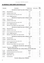
Page 44: ...hreshold 1000 26 modE 3 Operation mode of relay on 26 timE 3 The time period of the relay active state 0 0 26 unit 3 Unit of timE parameter SEC 26 rEF 3 Reference value offset of the relay threshold S...

Page 45: ...nsmission Std 30 Settings of access to the configuration parameters SECu menu A rEL1 Permission to changes of relay R1 threshold without of the user password knowledge oFF 31 A rEL2 Permission to chan...

Page 46: ...User manual COUNTER SLIK 94 46...

Page 47: ...User manual COUNTER SLIK 94 47...

Page 48: ...SIMEX Sp z o o ul Wielopole 11 80 556 Gda sk Poland tel 48 58 762 07 77 fax 48 58 762 07 70 http www simex pl e mail info simex pl...

Reviews: