User manual - DATA RECORDER SRD-99 and cooperating software
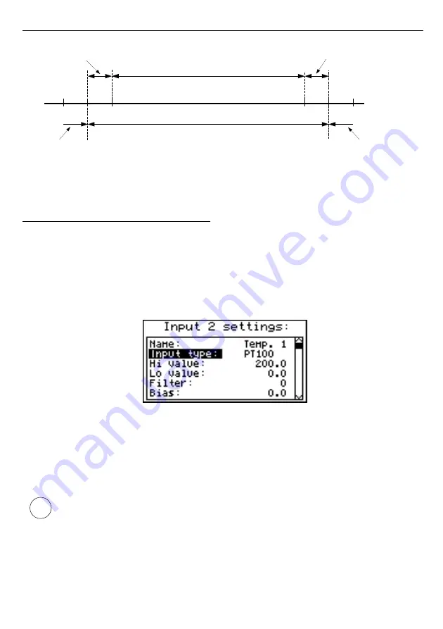
Fig. 7.25. Defining permissible measurement range for an example of settings of
“Upper ext.”
and
“Lower ext.”
parameters (for user range 2-10 V)
7.4.8.
”Input settings” menu (
RTD version
)
”Input type”
- type of input/sensor. The following options are available:
”inactive”
- input is not active
”PT100”
”PT500”
”PT1000”
- temperature sensor inputs,
user defined range
is defined
by “
Hi value
”and “
Lo value
” parameters.
Fig. 7.26.
”Inputs settings”
”Hi value”
”Lo value”
- These parameters define lower and upper limits of
user defined range
.
The percentage results, and the graph are scaled due to this range.
The
aforesaid parameters can be set in the range -999.9 ÷ 999.9. A negative
number can be input by entering a
'–'
mark (using
[^]
,
[v]
keys
).
The value of the
“Lo value”
parameter can be higher than the value of
“Hi value”
parameter. In such a case, the device automatically selects lower value as lower
limit, and higher value as upper limit of
user defined range
.
”Bias”
- offset (expressed in 0.1°C, range ± 9.9°C (or ±9,9°F)). This parameter allows
shifting of measurement scale, and express value added to calculated (measured)
result.
53
i
user defined range (2-10 V)
permissible measurement range
”
Lower ext.
” = 1 V
”Upper ext.”
= 1 V
measurement result is displayed regardless on
nominal range exceeding
display
message ”-Lo-”
2
display
message ”-Hi-”
1
0
10
11
12


