BA_PA-KL²-x-xx_EN_10
www.simon-protec.com
Date: 09.06.2020
Issue: 1.0 / 06.2020
info@simon-protec.com
Page 5
Mounting
INFORMATION
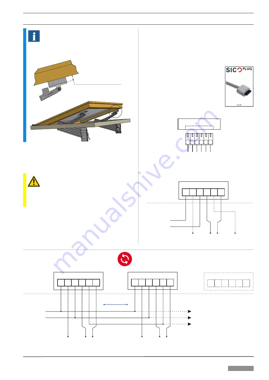
In case of a collision, spacers (up to 25 mm) are available.
Depending on the type of bracket kit and overlap of the
window they may be necessary.
D ( 1 : 4 )
C
A
B
C
D
E
F
G
H
1
2
3
4
A
B
C
D
E
F
G
H
1
2
3
4
5
6
5
6
SIMON PROtec
Systems GmbH
Medienstr. 8
D-94036 Passau
Tel. +49 851 98870-0
Fax. +49 851 98870-70
Blatt:
Revision:
Bezeichnung:
Teile-/Artikelnummer:
Zeichnungsnummer:
Allg. Toleranz:
Oberfläche:
DIN ISO 1302
DIN ISO 2768 - m
Projekt:
Material:
gezeichnet:
S.Kühling
Betriebsanleitung
2 EA-KL² Distanzstück
Fenst-0.1-006-5a
2 / 3
0.1
S2-Fenst-0.1-001-5
10.08.2018
geprüft / geändert:
von:
am:
10.08.2018
S.Kühling
am:
von:
konstruiert:
-
Gewicht:
Maßstab:
1 / 8
Blattgröße:
A3
Typ:
Schutzvermerk
ISO 16016 beachten!
von:
am:
distance block 25 mm
1.2. Electrical connection
See the attached sheet “
safety instructions and warranty
conditions
”!
ATTENTION
Unused wires must be electrically insulated.
The wires
C1
and
C2
must not be connected to each other
during normal operation.
1.2.1. Power supply
The power source must be dimensioned sufficiently for the
actuator. Voltage and current must fit the specifications on
the type label.
1.2.2. Feedback – volt-free contact
The normally open contact (NO1, NO2) is activated in di
-
rection “CLOSE” when the actuator is cut off in end position
“CLOSE”. The message is stroke-dependent and can be
evaluated as a “CLOSED” message.
1.2.3. Preparation for installation
Before starting the installation, the requi
-
red connection cable must be assembled.
For this purpose use the plug included
in the scope of delivery (see instructions
in the accessory bag with SICO PLUG).
For NSHEV according to EN 12101-2, the
silicone connecting cable approved by the
manufacturer must be used.
1.2.4. SICO PLUG assignment
Folding Arm²
S
C1
O
NO1
C2
NO2
1.2.5. Single operation
¾
Connect wires according to the the wiring diagram.
24 V DC
OPEN: S =
+
O =
–
CLOSE: pole-change
factory provided
volt-free contact
“CLOSE”
(max. 28 V / 2.0 A)
S
O
Actuator
O
S
NO1
C1
C2 NO2
insulate
electrically!
insulate
electrically!
1.2.6. Synchronous operation
¾
Connect wires according to the wiring diagram.
24 V DC
volt-free contact
“CLOSE”
(max. 28 V / 2.0 A)
volt-free contact
“CLOSE”
(max. 28 V / 2.0 A)
S
O
max. 10 m
I = n x I
total
max
n ≤ 4
1. Actuator
O
S
NO1
C1
C2 NO2
2. Actuator
O
S
NO1
C1
C2 NO2
n. Actuator
O
S
NO1
C1
C2 NO2
Master
Slave
Slave
O
S
C2
insulate
electrically!
factory provided
OPEN: S = +
O = -
OPEN
CLOSE: pole-change
insulate
electrically!


