Mounting
BA_PA-KL²-x-xx_EN_10
www.simon-protec.com
Date: 09.06.2020
info@simon-protec.com
Issue: 1.0 / 06.2020
Page 6
1.3. Setting options
You can set
single operation
or
synchronous operation
mode MASTER / SLAVE
via SICO LINK or manually (see
chapter 1.4.1)
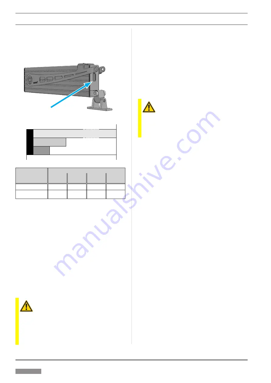
Figure 1: Interface for SICO LINK
Connection for SICO-USB-110
Figure 2: Stroke behaviour
mechanical “0”
electrical “0”
RESET-
range
electronical stroke
span
synchronous operation
stopping range
Actuator type
Folding Arm²
530
710
960
1200
PA-KL²-K
PA-KL²
PA-KL²-M PA-KL²-L
RESET-range
16 mm
21 mm
27 mm
34 mm
Synchronous operat.
stopping range
32 mm
42 mm
54 mm
68 mm
RESET-range
: When the actuator is cut off on overload
within the RESET-range, the electronic zero point will
be set new.
Synchronous operation stopping range
: If an actuator
cuts off in synchronous operation in direction CLOSE
within the
stopping range
, the remaining actuators
continue to run to the zero point until overload cut-off.
1.3.1. Synchronous actuators
The synchronous actuators of the PA-KL² series are identi
-
fied by the suffix “S” in the part number (e.g. PA-KL²-50/710-S
– M2 2001 S).
1.3.2. Zero point
/
RESET-range
It‘s necessary to reset the zero point, if the closed position
of the actuator is out of the RESET-range after installation.
(SICO LINK / RESET-run).
ATTENTION – Span
If the zero point is shifted due to a large pre-opening
(1)
, the
maximum span must not be exceeded.
span = pre-o max. stroke
(1)
Large pre-opening: Outside the permissible parameters. – Permissible pa-
rameters see 1.1.
1.3.3. Operating modes synchronous actuator
If a synchronous actuator is to be used as a single actuator,
the operating mode must be set to “Single operation”
(SICO LINK or RESET-run) – factory setting.
If several actuators are to be used in synchronous operation,
one actuator must be set to “Synchro Master” and the
re
maining actuators to “Slave” (SICO LINK or manual
MASTER
/
SLAVE setting).
1.4. Manual setting
1.4.1. MASTER / SLAVE setting
ATTENTION
Manual setting is only possible for two actuators connected
in parallel (one MASTER and one SLAVE).
For larger groups of actuators (more than one SLAVE),
a setup via SICO LINK is necessary.
¾
Drive the actuator in direction “CLOSE” (
S
= “
–
”
O
= “
+
”)
and let it cut off in the end position. If the actuator does
not reach the „mechanical ZERO“ position due to its
mounting position, a RESET-run must be performed.
¾
Leave the actuator energized!
¾
Connect the wires
C1
and
C2
directly together and dis-
connect them again after reaching the desired state
(MASTER or SLAVE).
When the wires
C1
and
C2
will be connected together,
a relay click can be heard.
After 5 seconds you can hear a relay click, the actuator
is set to MASTER with one connected SLAVE.
After 10 seconds a further relay click can be heard, the
actuator is now set to SLAVE.
¾
Disconnect the actuator from power supply!
¾
After individual programming, separate the wires
C1
and
C2
and connect the two actuators in accordance with
1.4.2. RESET-run
A RESET-run should be carried out,
●
if the opening width of the closed actuator at the window
is outside the RESET-range.
● if the MASTER
/
SLAVE setting needs to be reset.
¾
Disconnect the actuator(s) from power supply!
¾
Connect the wires
C1
and
C2
of each actuator directly
with each other.
¾
Drive each actuator in direction “CLOSE” (
S
= “
–
”
O
= “
+
”)
and let it be cut-off in the end position!
¾
Again disconnect the actuator(s) from power supply and
disconnect the wires
C1
and
C2
!
Ô
The zero point is set.
Ô
In case of “synchro capable” actuators, the operating
mode is reset to “single operation” by the RESET-run.
In this mode, the actuators can be operated standa
-
lone.


