


www.simondstore.com
Page
5
of
7
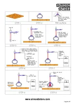
Assembly Instruction
Required Tools for Installation
Screw Driver
13mm wrench
17mm wrench
Unpacking:
Unwrap all the mentioned parts including identification sticker as above list with type of forge.
Step -1
Surface Preparation by placing Refractory Fire Brick/ Castable
Step-2
Place Forge Body over the prepared surface
Step-3
PART-A, PART-B & PART-C are pre-assembled parts of burner. At the top of the PART B you can see wing nut with
washer which can be rotated clockwise and anti-clockwise direction to regulate the air flow pressure while firing.
Step-4
Connect the burner at the top of the FORGE with the help of the coupling and adjustable screws.
Precautions:
Please make sure that burner’s nozzle end does not cross over inside insulation of forge
Step-5
Fill the gaps between burner and forge by using complementary ceramic fiber blanket
Step-6
Now connect PART D to the PART C, Which is gas hose pipe, it’s one end connects with Burner’s gas inlet pipe and
another with the Gas Pressure Regulator (PART F). Tighten the clamps at both ends.
Step-7
Now connect Gas regulator with the propane cylinder. Don’t forget that pressure regulator has left thread.
Step-8
Place the PART E inside the bottom of the Forge and over the ceramic fiber lining.
Step-9
Now Forge is ready for the firing.
Note:
Please ensure that gas hose pipe is not in contact with the forge body before operating the forge. Due to
hot surface of the body it will get damaged.


