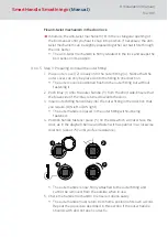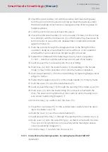
3. Insert inside handle horizontally into the outer fitting in the desired direc-
tion (DIN left or DIN right).
9
The internal handle is placed in the internal fitting without being
fastened.
4. Tighten the headless screw to fasten internal handle.
9
The inner door handle is now firmly linked to the SmartHandle.
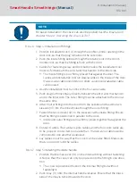
5. Check the handle mechanism to ensure it opens easily.
9
Repeat the procedure described in this section if the outer should
catch or jam.
NOTE
For easier installation, the cover can usually also be slid over the inlay later
in chapter "
Step 6: Fastening the covers [
".
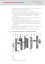
8.6.4.8 Step 6: Fastening the covers
Outer and inside covers are mounted in the same way:
1. Carefully press cover onto the door. Ensure that the cover is positioned
flat against the door without a gap and no cables are outside the cover.
2. Click inlay carefully into the outer cover, which is still pressed against
the door.
8.6.5 Disassembling DoorMonitoring components
The SmartHandle must be fully detached first before the bolt sensor and
fastening screw sensor can be dismounted.
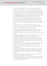
Dismount bolt sensor
1. Disconnect all cables from one another.
2. Conventional fastening system: Carefully press the snap-in adapter to-
gether and pull out through the profile cylinder opening.
3. Rotate bolt sensor 90º to the left, so that the button faces downwards.
4. Pull the bolt sensor out from the profile cylinder in the mortise lock hori-
zontally.
Dismount fastening screw sensor
1. Disconnect all cables from one another.
2. Grip the fastening screw head slit with a small screw driver.
3. Carefully prise out the fastening screw head.
4. Pull out the fastening screw head against the spring force.
SmartHandle
SmartIntego
(Manual)
8. Installation (manual)
86 / 160
Summary of Contents for SI:SmartHandle Series
Page 1: ...SmartHandle SmartIntego Manual 28 10 2020...
Page 25: ...6 5 Distances and door thicknesses SmartHandle SmartIntego Manual 6 Designs 25 160...
Page 131: ...SmartHandle SmartIntego Manual 8 Installation manual 131 160...
Page 132: ...9 Outer fitting is mounted SmartHandle SmartIntego Manual 8 Installation manual 132 160...
Page 136: ...2 Remove the uppermost battery SmartHandle SmartIntego Manual 8 Installation manual 136 160...
Page 137: ...3 Screw on the inside fitting SmartHandle SmartIntego Manual 8 Installation manual 137 160...
Page 145: ...10 Configuration See TechGuide WO SVCN SmartHandle SmartIntego Manual 10 Configuration 145 160...
Page 147: ...12 Signal See TechGuide WO SVCN SmartHandle SmartIntego Manual 12 Signal 147 160...


