background image

Assembly instructions for kit #8
All rights reserved. 2001 Simple Motors, LLC 

www.simplemotor.com

1

Assembly Instructions: Kit #8

With Kit #8 you have two choices:

You may build each of the motors one at a time using separate assembly instructions for

each motor (this is the easier way).

-or-

You may assemble all parts on the board as shown in the picture above and switch between

the 4 motor circuits by re-soldering connections between parts. This option is described

below.

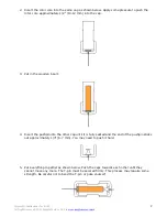
1. Insert the T-pin into one of the caps.

Summary of Contents for Kit 8

Page 1: ...ices You may build each of the motors one at a time using separate assembly instructions for each motor this is the easier way or You may assemble all parts on the board as shown in the picture above...

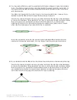
Page 2: ...into the cap 3 Put in the wooden insert 4 Insert the pushpin into the other cap until it is fully seated and the end of the pushpin sticks out approximately 1 4 6 7 mm You may need to push it hard 5 P...

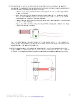
Page 3: ...marked by a cross Apply some glue to the middle of the disk and glue it to the cap with a shorter axle with the pushpin Slide two sequins as shown below The sequins act as a spacer between the disk an...

Page 4: ...f the rotor spins freely At this time or later you may take the rubber plug and fix it as shown below You can glue different things to the outer flat surface of the plug Try to be accurate redo this s...

Page 5: ...s possible Do not let the wire slide off the end of the electromagnet o Tape the second end of the wire using the same tape Both open ends of wire should be about 6 15 cm long o Clean about 3 8 10 mm...

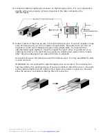
Page 6: ...ing a sharp knife You may bend the optointerrupter leads slightly to move them apart from each other If you did not use a soldering iron before it is a good idea to practice on soldering two pieces of...

Page 7: ...e in the middle of the slot as deep as possible without hitting the optointerrupter Wait for the glue to dry Hold the middle part of the rotor and rotate the cap that has the disk attached until one o...

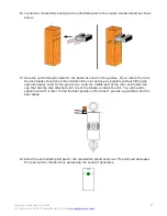
Page 8: ...ieces to a reed switch as shown in the first picture If you did not use a soldering iron before it is a good idea to practice on soldering two pieces of wire to each other See the Links page at our we...

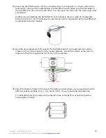
Page 9: ...eces with the length of 8 9 20 23 cm each Strip about 3 8 10 mm of insulation on each end of these wire pieces using a sharp knife Solder three wire pieces to the Hall Effect switch IMPORTANT Do not o...

Page 10: ...p 20 of Assembly Instructions for Kit 9 It minimizes the interference with a reed switch as the Hall Effect IC is extended to the top magnet 24 Glue the universal stand to the board The Hall Effect sw...

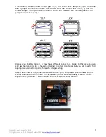
Page 11: ...es are inserted there is no jumper wire in this case Inspect your battery holder it may have different connections inside In this case you can still use the jumper wire in the same manner to get all 4...

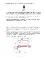
Page 12: ...available at our site to your motor It allows switching between all four motors with a simple turn of a knob A Reed Switch Motor Before connecting everything together connect both wires from the elect...

Page 13: ...e You may connect a capacitor as shown in the diagram above Do not forget to remove the insulation from the magnet wire before soldering It is not a required part for the motor to work but it may prol...

Page 14: ...romagnet wires to the positive red battery holder wire and the other electromagnet wire to the emitter as shown below If the electromagnet doesn t repel the permanent magnets away switch the wires If...

Page 15: ...e sure that in the starting position one of the blades is inside the optointerrupter slot and does not allow light from the LED to reach the phototransistor Briefly connect one electromagnet wire to t...

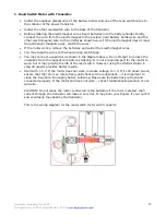
Page 16: ...Assembly instructions for kit 8 All rights reserved 2001 Simple Motors LLC www simplemotor com 16 This is the wiring diagram for the motor with an optical control...

Reviews: