Assembly instructions for kit #8
All rights reserved. 2001 Simple Motors, LLC
♦
♦
10
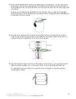
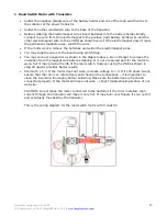
23. Insert the Hall Effect switch into the universal stand. For simplicity it is shown without the
reed switch, which will be located below the Hall Effect switch. Make sure that the leads of
the Hall Effect IC do not touch each other. You may push the wires into the slots using a flat
screwdriver.
Another way of attaching the Hall Effect IC to the stand is shown in step 20 of Assembly
Instructions for Kit #9. It minimizes the interference with a reed switch as the Hall Effect IC
is extended to the top magnet.
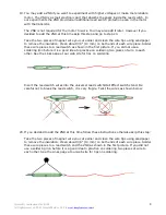
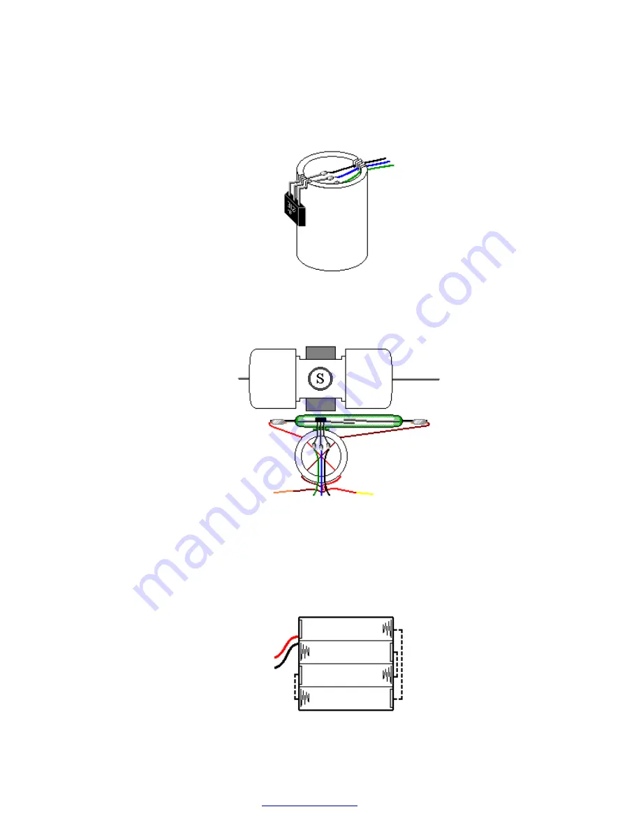
24. Glue the universal stand to the board. The Hall Effect switch and reed switch should be
located in front of the magnets at the closest distance. Check the rotation of the rotor to
make sure that the magnets do not hit any of the switches.
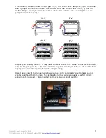
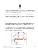
25. Attach the battery holder to the board. The battery holder allows you to experiment with 4
different voltage settings (1.5, 3, 4.5, and 6 V DC). You will need 4 AA size batteries.
To understand how the jumper wire works let's take a look at the connections inside a
typical battery holder:


