Assembly instructions for kit #8
All rights reserved. 2001 Simple Motors, LLC
♦
♦
13
B. Reed Switch Motor with Transistor.
•
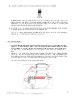
Solder the negative (black) wire of the battery holder and one of the reed switch wires to
the collector of the power transistor.
•
Solder the other reed switch wire to the base of the transistor.
•
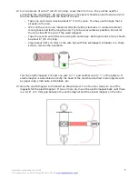
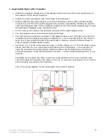
Before soldering the electromagnet wires insert batteries into the battery holder. Briefly
connect one wire from the electromagnet to the positive (red) battery holder wire and the
other electromagnet wire to the emitter as shown below. If the electromagnet doesn’t repel
the permanent magnets away, switch the wires.
•
If the motor works, remove the batteries and solder the electromagnet wires.
•
You may tape the wires to the board using scotch tape.
•
You may connect a capacitor as shown in the diagram above. Do not forget to remove the
insulation from the magnet wire before soldering. It is not a required part for the motor to
work, but it may prolong the life of the reed switch. However using the ZNR as shown in
step 20 usually provides better results.
•
Start with 1.5 V. If the motor does not work, increase voltage to 3 V. If it still doesn’t work,
ensure that the rotor can rotate freely and check all the connections – it is important to
clean the insulation thoroughly before soldering. Make sure the batteries are fresh and
connected properly. If the motor still does not work – check Troubleshooting section of our
web site.
CAUTION: Do not leave the motor connected to the batteries if the rotor is stalled. High
current through the transistor will make it very hot. It may burn your fingers if you touch it
and eventually may destroy the transistor.
This is the wiring diagram for the reed switch motor with transistor:


