background image

TM

TM

Summary of Contents for WyndenHall brooklin+max 3AXCHRP-07

Page 1: ...TM TM ...

Page 2: ...t 1 866 518 0120 ext 262 or go to www simpli home com parts request In order to assist you in a timely manner please have the following information ready Model _________________Part Number or Letter_____________________ Purchased at ____________Date of Purchase _________________________ If you wish to return the product please contact the retailer where the product was purchased ...

Page 3: ......

Page 4: ......

Page 5: ...PART DESCRIPTION 5 22 NEED HELP For help with assembly or if you are missing a part Please call customer service at 1 866 518 0120 ext 262 9 am to 4 pm EST LEFT SIDE QTY 1 F G RIGHT SIDE QTY 1 ...

Page 6: ...PART DESCRIPTION 6 22 NEED HELP For help with assembly or if you are missing a part Please call customer service at 1 866 518 0120 ext 262 9 am to 4 pm EST J K IL L1 IR H L2 L3 ...

Page 7: ...HARDWARE DESCRIPTION 7 22 2 4 ALLEN KEY QTY 1 Required Flathead screwdriver Phillips screwdriver Not Included FURNITURE TIP OVER RESTRAINT QTY 1 SET ...

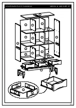
Page 8: ...COMPONENTS KEY DIAGRAM MODEL 3AXCHRP 07 B L1 D D F D D F D D G C G F J K H L R L R L R L2 L2 L3 ...

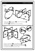
Page 9: ...ock Pins 5 to back of Drawer Front H 2 Align Cam Lock Pins with pre drilled holes and attach Drawer Sides IL IR 3 Insert two Cam Lock 5 into pre drilled holes on each Drawer Side IL IR 4 Use flathead screwdriver to secure Cam Locks H 5 K H L R L R ...

Page 10: ...ASSEMBLY MODEL 3AXCHRP 07 1 3 J K L R ...

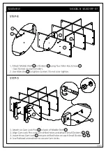
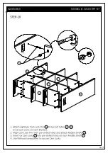
Page 11: ...Cam Lock Pins 5 to back of Middle Shelf F 2 Align Cam Lock Pins with pre drilled holes and attach Dividers D 3 Insert three Cam Lock 5 into pre drilled holes on each Divider D 4 Use flathead screwdriver to secure Cam Locks 1 3 D F D D F D 5 ...

Page 12: ...Cam Lock Pins 5 to back of Middle Shelf F 2 Align Cam Lock Pins with pre drilled holes and attach Dividers D 3 Insert three Cam Lock 5 into pre drilled holes on each Divider D 4 Use flathead screwdriver to secure Cam Locks 1 3 D F D 5 F D D ...

Page 13: ...ASSEMBLY MODEL 3AXCHRP 07 1 3 D F D 5 F L R ...

Page 14: ...ASSEMBLY MODEL 3AXCHRP 07 5 F F F L R ...

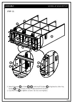
Page 15: ...STEP 11 15 22 L R ...

Page 16: ...ASSEMBLY MODEL 3AXCHRP 07 1 3 3 C G 2 ...

Page 17: ...ASSEMBLY MODEL 3AXCHRP 07 5 5 B D D L R ...

Page 18: ...ASSEMBLY MODEL 3AXCHRP 07 4 B L1 L2 L2 L3 ...

Page 19: ...6 D D D D D D R L ...

Page 20: ...7 7 ...

Page 21: ......

Page 22: ...TM TM WARRANTY ...

Reviews: