background image

15

Operation

WARNING

If you do not understand how a specific control
functions, or have not yet thoroughly read the
FEATURES & CONTROLS section, do so now.
Do NOT attempt to operate the tractor without
first becoming familiar with the location and
function of ALL controls.

STARTING THE  ENGINE

1. While sitting in the operator’s seat, engage the

parking brake and make sure the PTO switch is
disengaged and the motion control handles are
locked in the NEUTRAL position.

2.

NOTE: A warm engine may not require
choking.

Set the engine throttle control to FAST throttle
position. Then fully close the choke by pulling the
knob OUT fully.

3. Insert the key into the ignition switch and turn it to

START.

4. After the engine starts, gradually open the choke

(push knob down fully). Reduce to half throttle
speed and allow the engine to warm up.

Warm up the engine by running it for at least a minute
before engaging the PTO switch or driving the rider.

5.

After warming the engine, ALWAYS operate the
unit at FULL THROTTLE when mowing.

In the event of an emergency the engine can be
stopped by simply turning the ignition switch to
STOP.

Use this method only in emergency situations.

For normal engine shut down follow the procedure
given in STOPPING THE RIDER.

STOPPING THE RIDER AND
ENGINE

1. Returning the ground speed control levers to the

middle position will stop tractor movement. Pivot
the levers outward and lock them in NEUTRAL.

2. Disengage the PTO by pushing down on the PTO

switch.

3. Engage the parking brake by pulling the handle up

until it locks into position.

4. Move the throttle control to mid-throttle position

and turn the ignition key to OFF. Remove the key.

PUSHING THE RIDER BY HAND

1. Disengage the PTO, engage the parking brake,

turn the ignition OFF, and remove the key.

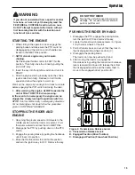
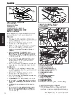
2. Locate the transmission release levers (A, Figure

2) by the rear wheels of the unit.

3. Pull both levers back and out so that they lock in

the disengaged (free-wheel) position (C).

4. Disengage the parking brake.

The tractor can now be pushed by hand.

5. After moving the tractor, re-engage the

transmissions by pulling the transmission release
levers rearward and inward to release them from
the disengaged position and then allow them to
move to the engaged (drive) position (B).

DO NOT TOW RIDER

Towing the unit will cause transmission
damage. Do not use another vehicle to
push or pull this unit.

Figure 2. Transmission Release Levers
A. Transmission Release Levers
B. Engaged Position (Drive Position)
C. Disengaged Position (Free-wheel Position)

Operation

A

B

C

Summary of Contents for 5900660

Page 1: ...er with 50 Mower 5900684 ZT3000B2450CE Simplicity 24HP B S ZT3000 Zero Turn Rider with 50 Mower CE Export 5900681 355ZB2444 Snapper 24HP B S 355Z Zero Turn Ridier with 44 Mower 5900682 355ZB2450 Snapp...

Page 2: ...THIS PAGE INTENTIONALLY BLANK FOR PLACEMENT ONLY DO NOT PRINT...

Page 3: ...rd Power Products Group Copyright 2007 Briggs Stratton Corporation Milwaukee WI USA All rights reserved The Simplicity logo is a trademark of Briggs Stratton Corporation Milwaukee WI USA Contact Infor...

Page 4: ...r 27 Engine Maintenance 27 Check Fill Transmission Oil 28 Transmission Oil Filter Change 28 Battery Maintenance 29 Storage 29 Troubleshooting Adjustments Service 30 Troubleshooting the Rider 30 Troubl...

Page 5: ...ely done with the equipment you have chosen ask a professional contact your local authorized dealer Read the Manual The operator s manual contains important safety information you need to be aware of...

Page 6: ...des These blades can pick up and throw debris that could seriously injure a bystander Be sure to clean up the area to be mowed and remove objects that could be thrown by the blade BEFORE you start mow...

Page 7: ...el indoors in an enclosed trailer garage or any other enclosed area that is not well ventilated Gasoline spills should be cleaned up promptly and before operation begins Gasoline should be stored only...

Page 8: ...re are present intact and secure Replace worn or damaged parts 24 Disengage attachments before refueling removing an attachment making adjustments unless the adjustment can be made from the operator s...

Page 9: ...do not operate on it Control of a walk behind or ride on machine sliding on a slope will not be regained by the application of the brake The main reasons for loss of control are insufficient tire gri...

Page 10: ...n necessary Ensure clamps grip hoses firmly over the filter after installation 12 Do not use gasoline containing METHANOL gasohol containing more than 10 ETHANOL gasoline additives or white gas becaus...

Page 11: ...x XXX BRIGGS STRATTON CORP YARD POWER PRODUCTS GROUP MUNNSVILLE NY 13409 USA S S A A M M P P L L E E S S A A M M P P L L E E North American CE Models CE Models Only Mfg No xxxxxxx S N xxxxxxxxxx xxxxx...

Page 12: ...ly read and obeyed Personal bodily injury can result when these instructions are not followed The information is for your safety and it is important The safety decals below are on your rider and mower...

Page 13: ...s a safety test do not operate it See your authorized dealer Under no circumstance should you attempt to defeat the purpose of the safety interlock system EXPORT MODELS ONLY SAFETY INTERLOCK SYSTEM Th...

Page 14: ...y from belts and pulleys Danger Machine Rollover Do not operate on any slopes when wet or slippery Do not operate near drop offs or near water Safety Icons The alert symbol is used to identity safety...

Page 15: ...tle Choke Close the choke for cold starting Open the choke once the engine starts A warm engine may not require choking Move the lever forward to close the choke Move the lever back to open the choke...

Page 16: ...HAND for operational information Seat Adjustment Lever The seat can be adjusted forward and backward Move the adjustment lever towards the left slide the seat to the desired position and release the...

Page 17: ...engage the parking brake disengage the PTO stop the engine and remove the key To reduce fire hazard keep the engine tractor and mower free of grass leaves and excess grease Do not stop or park tracto...

Page 18: ...tions For normal engine shut down follow the procedure given in STOPPING THE RIDER STOPPING THE RIDER AND ENGINE 1 Returning the ground speed control levers to the middle position will stop tractor mo...

Page 19: ...ng the control levers inward BASIC DRIVING Forward Travel Practice Gradually move both ground speed control levers evenly FORWARD from neutral Slow down and repeat NOTE Straight forward travel takes p...

Page 20: ...erienced with operating the Zero Turn rider you will learn more maneuvers that will make your mowing time easier and more enjoyable Remember the more you practice the better your control of the Zero T...

Page 21: ...and wait for all moving parts to stop 2 Remove the cutting height pin and lower the attachment lift to its lowest position 3 Pivot the front wheels out of the way and slide the mower deck under the un...

Page 22: ...l condition Cutting the grass too short causes weak thin grass plants which are easily damaged by dry periods and pests Cutting too short is often more damaging than allowing the grass to be slightly...

Page 23: ...ast using a slower ground speed will improve the cutting efficiency of the blades and prevents many common cutting problems Use an appropriate ground speed for the thickness and height of the grass yo...

Page 24: ...not function properly if the grass is wet or if the grass is simply to high to cut Even more than normal mowing mulching requires that the grass be dry and the the appropriate amount is cut Do not use...

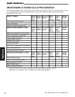
Page 25: ...h Use Every 5 Hours Every 25 Hours Every 100 Hours Every 200 Hours Spring Fall Check Rider Mower for loose hardware Check Clean Engine Cooling Fins Check Adjust PTO Clutch Lubricate Rider Mower Clean...

Page 26: ...ion LUBRICATION Lubricate the unit at the following lubrication points shown in Figure 16 Grease front caster wheel axles front caster yokes roller straps deck lift pivots mower deck idler arm pivot m...

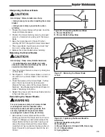
Page 27: ...nicks sharpen the blades See Sharpening the Mower Blades Figure 17 Loosening the Mower Blade for Removal CAUTION Avoid injury Mower blades are sharp Always wear gloves when handling mower blades or wo...

Page 28: ...ced See Sharpening the Mower Blades for proper sharpening instructions 4 Repeat the process until the mower blade remains in the horizontal position Reinstalling the Mower Blades 1 Reinstall each mowe...

Page 29: ...ow the filter to catch spilled fuel 3 Using pliers open and slide the hose clamps from the fuel filter C Figure 24 4 Remove the hoses from the filter 5 Install the new filter in the proper flow direct...

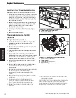
Page 30: ...age position route around to the front of the engine to retain the hose during normal operation 5 Place an absorbent shop cloth under the engine oil filter B Remove the oil filter and discard 6 Using...

Page 31: ...r the oil has drained thread the new filter onto the filter base until the gasket makes contact then tighten 3 4 of a turn more 5 Reinstall the filter guard with the three 1 4 filter guard screws 6 Us...

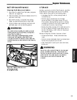
Page 32: ...gure 28 4 Coat the cable ends and battery terminals with petroleum jelly or non conducting grease STORAGE Before you store your unit for the off season read the Maintenance and Storage instructions in...

Page 33: ...hot allow it to cool then refill the fuel tank 4 Engine flooded 4 Move choke control to closed position 5 Fuse blown 5 Replace fuse 6 Battery terminals require 6 Clean the battery terminals cleaning...

Page 34: ...roperly attached 1 See authorized service dealer for repair or damaged Engine stalls easily with 1 Engine speed too slow 1 Set to full throttle mower engaged 2 Ground speed too fast 2 Decrease Ground...

Page 35: ...vel the deck correctly 2 Tires are not properly inflated 2 Check and inflate the tires 3 Blades are damaged 3 Replace the blades 4 Deck shell is damaged 4 Repair or replace the deck 5 Mower spindle is...

Page 36: ...MENT The control levers can be adjusted in three ways The alignment of the control levers the placement of the levers how close the ends are to one another and the height of the levers can be adjusted...

Page 37: ...tting height adjustment pin A NEUTRAL ADJUSTMENT If the unit creeps forward or backward with the control levers in their neutral positions see your dealer SPEED BALANCING ADJUSTMENT If the rider veers...

Page 38: ...y move the o ring against the adjustment collar to prevent the collar from loosening during operation Figure 34 Suspension Adjustment A Front Shock Adjustment Collar A Figure 33 Parking Brake Adjustme...

Page 39: ...ace and armature face just contacts the gauge 5 Check the windows for an equal amount of tension when the gauge is inserted and removed and make any necessary adjustments by tightening or loosening th...

Page 40: ...ground to the front tip of the center blade and from the ground to rear tips of left hand and right hand blades Figures 38 40 The front tip of the center blade should be 1 4 6mm higher than rear tips...

Page 41: ...n the correct level is achieved hold the eccentric with a wrench and tighten the locknut Repeat step 4 if necessary Figure 41 Roller Bar Leveling A Eccentric and Locknut A MOWER BELT REPLACEMENT 1 Par...

Page 42: ...n nut 6 Reinstall the PTO drive belt Figure 44 Hydraulic Pump Drive Belt Replacement Shown from Below A Pump Drive Belt B Crankshaft Pulley C Transmission Pulley D Idler Pulleys stationary E Idler Pul...

Page 43: ...orque values are also included For applicable manuals currently available for your model contact our Customer Publications Department at 262 284 8519 Simplicity 866 313 6682 Snapper Have the model and...

Page 44: ...41 Notes...

Page 45: ...odel 44M777 0121 E1 Oil Capacity 4 US pt 1 9 L w Filter CHASSIS Fuel Tank Capacity 6 5 Gallons 24 6 L Rear Wheels Tire Size 20 x 8 00 10 Inflation Pressure 15 psi 1 03 bar Front Wheels Tire Size 11 x...

Reviews: