34
www.simplicitymfg.com | www.snapper.com
Troubleshooting
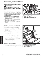
Figure 32. Cutting Height Adjustment
A. Cutting Height Adjustment Pin
B. Deck Lift / Cutting Height Lever
C. Transport Release Lever
B
C
A
CUTTING HEIGHT ADJUSTMENT
The cutting height adjustment pin (A, Figure 32)
controls the mower cutting height. The cutting height
is adjustable between 1-1/2” (3,8 cm) and 4-1/2”
(11,4cm). Pulling the lever back fully locks the control
in transport position.
To adjust cutting height:
1. Pull the adjustment lever (B) back fully until it locks
in transport position.
2. Remove the cutting height adjustment pin (A) and
insert it into the desired hole.
3. Pull back on the adjustment lever (B), squeeze the
smaller transport release lever (C), and allow the
lever to move forward until it is supported by the
cutting height adjustment pin (A).
NEUTRAL ADJUSTMENT
If the unit creeps forward or backward with the control
levers in their neutral positions, see your dealer.
SPEED BALANCING ADJUSTMENT
If the rider veers to the right or left when the ground
speed control levers are in the maximum forward or
reverse position, the top speed of each of these levers
can be balanced by turning the adjustment bolt(s) (A
& C Figure 31). Only adjust the speed of the wheel
that is traveling faster.
TO REDUCE THE SPEED OF THE FASTER WHEEL
1. Loosen the jam nut securing the top speed
adjustment bolt (A, C).
2. Turn the top speed adjustment bolt COUNTER-
CLOCKWISE to reduce the speed.
3. Retighten the securing nut when adjustment is
complete.
WARNING
DO NOT adjust the rider for a faster overall
speed forward or reverse than it was designed
for.
Troubleshooting, Adjustments, & Service
Figure 31. Top Speed Adjustment
A. Forward Top Speed Adjustment Bolt
B. Control Lever Base
C. Reverse Top Speed Adjustment Bolt
A
B
C

