background image

Intermediate Frame Snowthrowers

TP 300-4681-01-IW-SN

09/2007

10

Perform
Safety Checks

Check Engine Controls

1. Make sure all safety guards are in place and all nuts,

bolts, clips, cotter pins and wires are secure.

2. Check to make sure spark plug wire is attached.

3. Check all controls for proper operation:

a. The engine should stop when the key is removed.

b. The throttle should control the engine speed and
stop the engine when moved to the STOP position.

c. The fuel shut-off valve should stop the flow of fuel
to the engine

d. The recoil starter or electric starter (if equipped)
should crank the engine when activated.

4. Check the engine area for oil or gasoline leaks.

Correct any problems in accordance with the engine
manufacturers instructions.  

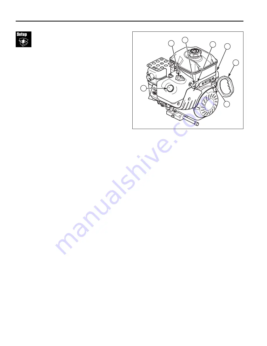
Figure 1.  Engine Controls
A. Electric Start Button (Select Models)
B. Fuel Valve (Select Models)
C. Starter Handle
D. Primer Button
E. Engine Key
F. Choke Knob
G. Stop Switch

Snow

Series

C

D

E

B

F

A

G

Summary of Contents for 9GT

Page 1: ...ee WI USA All Rights Reserved Intermediate Frame Snowthrowers Mfg No Description 1695302 SMI I1924E 9GT B S 24 1695311 SMI I1924EX 9GT B S 24 CE 1695410 SMI I1924EX 9GT B S 24 CE 1695313 SNP I1924E 9G...

Page 2: ...e your authorized dealer for recommendations counter weights to improve stability Travel up and down slopes not across Remove obstacles such as rocks tree limbs etc Watch for holes ruts or bumps Uneve...

Page 3: ...ation 7 10 Auger Shaft Shear Pins 8 11 Deflector Hinge Lubrication 8 12 Axles and Control Lever Lubrication 8 13 Spout Rotator Lubrication 9 14 Hand Control Lubrication 9 15 Engine Lubrication 9 Perfo...

Page 4: ...Intermediate Frame Snowthrowers TP 300 4681 01 IW SN 09 2007 4 1 2 Size PSI bar 15 x 5 0 6 20 1 38 16 x 4 8 8 14 96 2 x...

Page 5: ...Intermediate Frame Snowthrowers 09 2007 5 TP 300 4681 01 IW SN 3 5 16 18 x 2 5 16 18 x 2 3 4 5 16 18 5 16 A C B B A B A 4 5 lb ft 7 Nm C D D D...

Page 6: ...Intermediate Frame Snowthrowers TP 300 4681 01 IW SN 09 2007 6 6 A D C B 5 5 16 18 x 1 1 2 5 16 18 A B A B...

Page 7: ...Intermediate Frame Snowthrowers 09 2007 7 TP 300 4681 01 IW SN 7 3 2 2 1 8 9 1...

Page 8: ...Intermediate Frame Snowthrowers TP 300 4681 01 IW SN 09 2007 8 11 12 10...

Page 9: ...Intermediate Frame Snowthrowers 09 2007 9 TP 300 4681 01 IW SN 15 13 14 16...

Page 10: ...should control the engine speed and stop the engine when moved to the STOP position c The fuel shut off valve should stop the flow of fuel to the engine d The recoil starter or electric starter if eq...

Page 11: ...on when released If controls do not function properly perform the appropriate adjustment as shown in the Adjustment Section 7 The auger is secured to the shaft by shear pins which will break if the au...

Page 12: ...er must not be engaged unless auger control is depressed 5 With engine running fully depress auger control the auger should engage and run normally 6 Release auger control Auger must stop within 5 sec...

Page 13: ...Note If the cable is too slack the unit will not drive If the cable is too tight the drive will be engaged without push ing the handle down 4 Slide the cable boot A over the cable adjustment bracket...

Page 14: ...es worn it can be adjusted by loosening the nuts and bolts attaching it to the snowthrower making the adjustment and tightening the hardware It may also be replaced by removing the mounting nuts and b...

Page 15: ...ulley towards belt about 1 8 inch 3mm 4 Tighten nut D 5 Engage auger drive clutch Check tension on belt opposite idler pulley Belt should deflect about 1 2 inch 12 5 mm with moderate pressure see Figu...

Page 16: ...ne D Auger Drive Belt E Traction Drive Spring F Traction Drive Pulley Engine G Traction Drive Pulley H Impeller Pulley I Swing Plate Axle Rod J E Ring K Auger Idler Pulley L Traction Drive Idler Pulle...

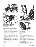
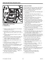
Page 17: ...ulley Replace the auger drive belt with an original factory replacement belt available from an authorized service center 14 Install the new auger drive belt D onto the impeller pulley B A Figure 14 Ro...

Page 18: ...od I 5 Remove the swing plate axle rod I to allow the swing plate A Figure 12 to pivot forward 6 Remove the old traction drive belt A from the trac tion drive pulley G and from the traction drive pull...

Reviews: