background image

Adjustments 8 Service

To avoid serious injury, perform adjustments
only with engine stopped, key removed and trac-
tor on level ground.

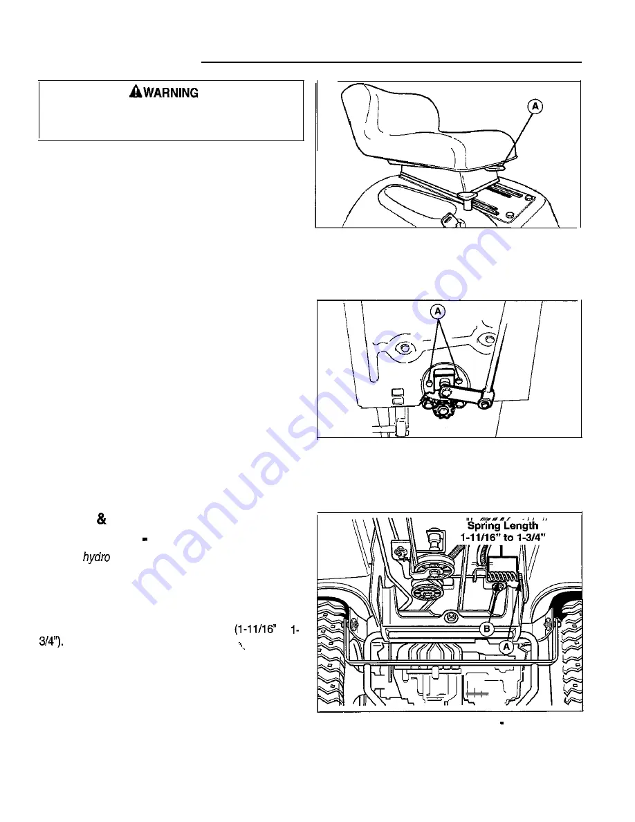
SEAT ADJUSTMENT

The seat can be moved forward and back by moving the

lever (A, Figure 26) underneath the front of the seat, then
positioning the seat as desired.

Figure 26. Seat Adjustment

A. Seat Adjustment Lever

STEERING GEAR ADJUSTMENT

If there is excessive slack in the steering system, the steer-
ing gear back lash can be eliminated by re-indexing the it

to the steering shaft gear with the following adjustment.

1. Loosen the two capscrews (A, Figure 27)

2. Push the bracket so that the gear teeth are closely

meshed.

3. Retighten the nuts after adjustment.

BRAKE 

 BRAKE SPRING

ADJUSTMENT   HYDRO

Note: All 

 brake adjustment is accomplished

through brake spring adjustment.

1. Fully depress brake pedal and lock parking brake.

2. See Figure 28. With the tractor parked on a level sur-

face adjust the brake rod nut (A) until spring (B) is

compressed to a length of 1.69”-1.75” 

 to 

3. Check the adjustment by backing the tractor up a hill,

engaging the parking brake, and shutting off the
engine. While seated in the operator’s position park
the tractor for at least 30 seconds and watch for

movement.

If the parking brake does not hold, tighten the spring.

If the parking brake cannot be engaged, loosen the
brake spring.

Figure 27. Steering Gear Adjustment

A. Capscrews

Figure 26. Brake Spring Adjustment   Hydro Models

A. Nut

B. Spring

2 4

0 1

Summary of Contents for Regent 1693264

Page 1: ...OPERATOR S MANUAL Regent Sport Series 14HP Hydro Tractor Mfg No Description 1693264 Regent Florida Gator 14HP Hydro 38 Mower Decks Mfg No Description 1693266 36 Mower Deck Rev 0 9 TP LOO 2079 OL RG S G ...

Page 2: ...es 18 STORAGE 19 Temporary Storage 19 Long Term Storage I9 Starting After Long Term Storage I9 TROUBLESHOOTING 20 Troubleshooting The Tractor 2 0 Troubleshooting The Mower 21 BAlTERY SERVICE 22 Checking the Battery Voltage 22 Charging A Completely Discharged Battery 2 2 Jump Starting with Auxiliary Booster Battery 2 2 ADJUSTMENTS SERVICE 24 Seat Adjustment 24 Steering Gear Adjustment 24 Brake Brak...

Page 3: ...tractor and mower deck manufacturer numbers and engine serial number in the space provided for easy reference l The Tractor I D tag is located on the left side of the frame as shown below l The Mower Deck I D tag is also on the left side on top of the mower deck l For location of Engine Serial Number refer to the Engine Owner s Manual Be sure to fill out and return the Warranty Registration Card s...

Page 4: ...control and tip over accidents which can result in severe injury or death All slopes require extra caution If you cannot back up the slope or if you feel uneasy on it do not mow it A WARNING SLOPE OPERATION Never operate on slopes greater than 30 percent 16 7 which is a rise of three feet vertically in 10 feet horizontally When operating on slopes that are greater than 15 percent 6 5 but less than...

Page 5: ... gasoline and other fuels They are flammable and vapors are explosive a Use only an approved container b Never remove gas cap or add fuel with the engine running Allow engine to cool before refueling Do not smoke c Never refuel the unit indoors l Never run a unit in an enclosed area l Keep nuts and bolts especially blade attachment bolts tight and keep equipment in good condition l Never tamper wi...

Page 6: ...d mower should be carefully read and obeyed Personal bodily injury can result when these instructions are not followed The information is for your safety and it is important The safety decals below are on your tractor and mower If any of these decals are lost or damaged replace them at once See your local dealer for replacements These labels are easily applied and will act as a constant visual rem...

Page 7: ...tment Lever 1 Brake Pedal Brake Pedal I Forward Direction Pedal I Forward Direction Pedal I Rear Direction Pedal I Rear Direction Pedal igure 1 Tractor Mower Controls Hydro Model CONTROLS GEAR MODEL A Steering Wheel B Throttle C Parking Brake Knob 0I Ignition Key Switch E Headlight Switch _ FP T O Ek _ _ ctric Clutch Switch G i Mower Height Adjustment Lever HI Clutch Brake Pedal I Gear selector L ...

Page 8: ...16 7 which is a rise of three feet vertically in 10 feet horizontally When operating on slopes that are greater than 15 percent 5 5 but less than 30 percent use front counterweights and rear wheel weights see your dealer Select slow ground speed before driving onto slope In addition to front and rear weights use extra caution when operating on slopes with rear mounted grass catcher Mow UP and DOWN...

Page 9: ...engine may not require choking Disengage the PTO by pushing the switch all the way down F Figures 1 2 On hydro models with your foot off the pedals I J Figure 1 the tractor is in the neutral position On gear models put the gear selector I Figure 2 in neutral Insert the key into the ignition switch D Figure 1 2 and turn it to START Figure 3 Clutch Brake Pedal Operation A Clutch Brake Pedal Gear Mod...

Page 10: ...G On gear model press the clutch brake pedal H Note To drive the tractor the release lever most be Figure 2 down only far enough to disengage the moved completely forward and pushed down into locked clutch to make a gradual stop For a more rapid stop position to engage the transmission press pedal down fully to apply the brake 2 Engage the parking brake by pulling up on the knob C Figure 1 2 with ...

Page 11: ... tractor 6 Install the mower in reverse order of removal NOTE When installing rod A Figure S turning the front wheels slightly et or right helps to align the holes ADJUSTING MOWER CUlTlNG HEIGHT GAUGE WHEELS NOTE Perform adjustment on a hard level surface such as a concrete floor 1 Set the mower height adjustment lever A Figure 8 to the desired cutting height 2 Remove the pin clip B Figure 8 from ...

Page 12: ...preferably in the late afternoon when the temperatures are cooler l Where possible change patterns occasionally to eliminate matting graining or a corrugated appear ance l For wet grasses grasses prone to wheel tracking and for collecting clippings a Use sharp blades b Adjust deck l 4 higher in front than in rear c Run at maximum engine speed but slow ground speed d Clean deck of built up material...

Page 13: ... a cutting height that is matched to your mowing conditions and prefer ences Since mulching requires more horsepower than side discharging using a slower ground speed is impor tant for proper mulching operation Clippings Are Beneficial A common misconception about clippings is that they automatically lead to thatch However clippings pro duced by mulching methods actually contribute to a healthy la...

Page 14: ...ades 1 6 Inspect or replace spark plug s Check belt tension See the engine manufacturer s owner s manual Change original engine oil after first 5 hours of operation I More often in hot over 85 F 30 C weather or dusty operating conditions I Change the transmission oil after the first 50 hours then every 250 hours Use SAE low 30 with a minimum API rating of CD TIRE PRESSURE Tire pressure should be c...

Page 15: ...Remove hoses from filter 3 Install new filter in proper flow direction in fuel line Secure with hose clamps See warning at beginning of procedure A WARNING Do not remove fuel filter when engine is hot as spilled gasoline may ignite DO NOT spread hose clamps further than necessary Ensure clamps grip hoses firmly over filter after installation OIL FILTER CHANGE Refer to engine manual for specific oi...

Page 16: ...t adjustment linkage Generally all moving metal parts should be oiled where contact is made with other parts Keep oil and grease off belts and pulleys Remember to wipe fittings and sur faces clean both before and after lubrication Not all greases are compatible Simplicity Jiffy Lube Lithium Grease is recommended automotive type lithium grease may be used when this is not available Unit pictured fr...

Page 17: ...k stand to support the unit while tires are approximately 1 2 off the ground performing service and chock remaining wheels NOTE For overall unit stability during service do not to prevent the unit from rolling off the supports jack rear end higher than required for wheel removal Never work under or around an elevated unit that 4 Support the rear of the unit on jackstands positioned is not properly...

Page 18: ... transmission with oil up to the top notch see Figure 19 inset 6 Replace the spring and fill plug Reinstall the battery See Battery Maintenance BATTERY MAINTENANCE Figure 20 Draining the Hydro Transmission Be careful when handling the battery Avoid spilling electrolyte Keep flames and sparks Checking the Battery Fluid 1 Raise the seat 2 Remove the battery filler cap C Figure 21 Fluid must be even ...

Page 19: ...blade edge If blade is severely damaged it should be replaced 5 Balance the blade as shown in Figure 23 Center the blades hole on a nail lubricated with a drop of oil A balanced blade will remain level 6 Reinstall each blade with the tabs pointing up toward deck as shown in Figure 24 Secure with a capscrew spring washer and hex washer Use a wooden block to prevent blade rotation and torque capscre...

Page 20: ...ace and fully charged about once a month If battery is left in tractor discon nect the negative cable 10 Drain fuel system completely or add a gasoline stabilizer to the fuel system If you have chosen to use a fuel sta bilizer and have not drained the fuel system follow all safety instructions and storage precautions in this man ual to prevent the possibility of fire from the ignition of gasoline ...

Page 21: ... starter motor faulty 9 Repair or replace See authorized dealer 10 Safety interlock switch or IO Replace as needed See authorized module faulty service dealer 11 Spark plug s faulty fouled 11 Clean and gap or replace See engine manual or incorrectly gapped 12 Water in fuel 12 Drain fuel refill with fresh fuel 13 Gas is old or stale 13 Drain fuel replace with fresh fuel 14 Clutch Brake pedal not de...

Page 22: ...r tires not inflated 2 See Maintenance Section Mower cut is rough looking Engine stalls easily with mower engaged Excessive mower vibration 2 equally or properly Ground ipeed too fast 1 3 Blades are dull Engine speed too slow 4 Mower drive belt slipping because it is oily or worn 5 Blades not properly fastened to arbors 1 Engine speed too slow 2 Ground speed too fast 3 Cutting height set too low 4...

Page 23: ...lectrolyte is 1 250 or higher and the electrolyte temperature is at least 60 F The best method of making certain a battery is fully charged but not over charged is to measure the specific gravity of a cell once per hour The battery is fully charged when the cells are gassing freely at low charging rate and less than 0 003 change in specific gravity occurs over a three hour period JUMP STARTING WIT...

Page 24: ...ne all fill vents on the battery If ice can be en or if the electrolyte fluid cannot be seen do not attempt to start with jumper cables as long as the battery remains frozen A WARNING I To avoid engine damage do not disconnect bat tery while engine is running Be sure terminal connections are tight before starting A WARNING For your personal safety use extreme care when jump starting Never expose b...

Page 25: ... are closely meshed 3 Retighten the nuts after adjustment BRAKE BRAKE SPRING ADJUSTMENT HYDRO Note All hydra brake adjustment is accomplished through brake spring adjustment 1 Fully depress brake pedal and lock parking brake 2 See Figure 28 With the tractor parked on a level sur face adjust the brake rod nut A until spring B is compressed to a length of 1 69 1 75 l 11 16 to I 3 4 3 Check the adjus...

Page 26: ... between the lever 8 and the stop C as shown in the inset 3 To adjust clearance turn nut D clockwise to decrease the gap or turn nut counterclockwise to increase the gap 4 See Figure 30 Set the parking brake Loosen or tighten adjustment nut E to achieve a 2 3 8 to 2 i 2 compressed spring length as shown A Brake Rod B Brake Cam Lever c stop D Adjustment Nut E Spring Adj Nut A Nut 6 Spring 0 1 2 5 ...

Page 27: ...easure the distance between the outside tips of each blade and the ground If there is more than i 8 3mm difference between the mea surements on each side proceed to step 5 If the dif ference is i 8 3mm or less proceed to step 6 5 See Figure 32 Loosen the outside nut A and tap tite screw C then turn the eccentric nut 8 to raise or lower the left side of the deck When the mower deck is level hold th...

Page 28: ...ee your dealer MOWER BELT REPLACEMENT 38 Mowers 1 Park the tractor on a level surface Disengage the PTO turn off the engine and set the parking brake Remove the key 2 Remove the mower deck from the tractor See Mower Installation Removal in the Operation section 3 Remove the old belt and install the new belt over the pulleys as shown in Figure 35 4 Reinstall the mower deck on the tractor 44 Mowers ...

Page 29: ...ing B Sleeve D Capscrew 5 On gear models disconnect the wires from the neu tral switch on the transmission On hydro models loosen the belt stop on the trans mission pulley Belt stop hardware is located on the inside of RH frame Move belt stop out of the way Belt stop should be positioned 118 from belt when new belt is installed and hardware is tightened 6 Carefully slide belt over transmission pul...

Page 30: ......

Page 31: ......

Page 32: ......

Page 33: ......

Page 34: ......

Reviews: