11
SimpliFire • SF-ALL40-BK, SF-ALL48-BK, SF-ALL60-BK, SF-ALL84-BK Service Manual • 2040-960 Rev. G • 5/20
WARNING! Risk of Damage or Personal Injury!
Do
not use supplied masonry anchors on hollow walls,
sheathed with wood, gypsum wallbaord, drywall or other
materials.
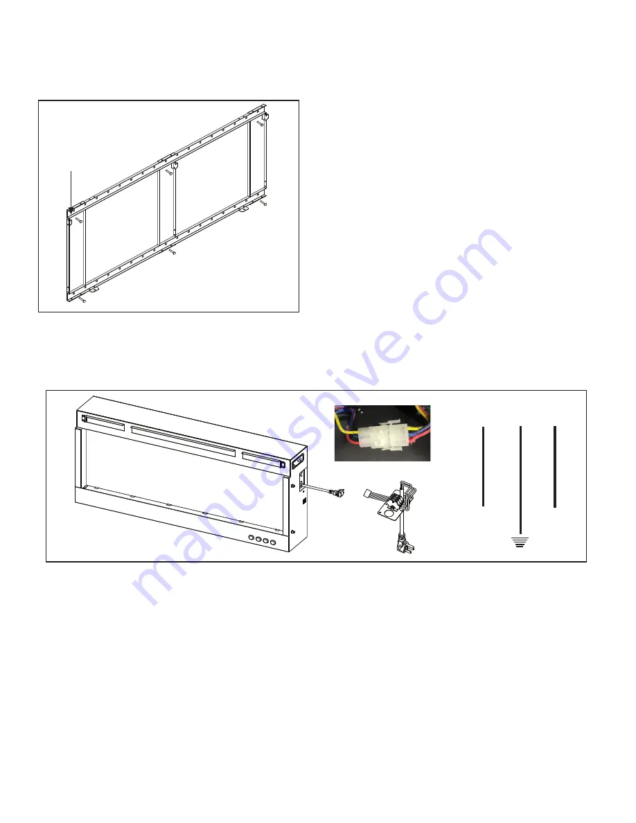
Figure 31. Bracket Attachment
Mounting Hooks
Point Up
Note:
For non-masonry walls,
at least
two
mounting points
(screws ST6X50) must align
with structural framing member.
WARNING! Risk of Fire, Electrical Shock and Injury!
Ensure the power cord is not installed so that it is pinched
or against a sharp edge and ensure that the power cord is
stored or secure to avoid tripping and snagging.
Figure 32. Optional Power Cord Assembly Installation
L
N
RED
BLUE
Wire Diagram
YELLOW / GREEN
Power Cord Installation
The appliance power cord has a three pin NEMA-5-15P
plug. The power cord should not be used unless a
grounded receptacle is available.
1. Remove the terminal block cover plate located on
the right end of the appliance.
2. Disconnect the terminal block from the three wires
inside the appliance. Wires are released by discon-
necting the three conductor wire connector. Discard
the terminal block cover plate.
3. Connect the three conductor wire connector to the
connector on the block supplied with the power cord
kit. See Figure 32.
4. Replace cord kit terminal block cover plate
and retaining screws. Plug cord into nearest outlet.


