SimpliFire • SF-WM36, SF-WM58, SF-WM70, SF-WM94 Service Manual • 2040-908 Rev. D • 1/19
2
2
1
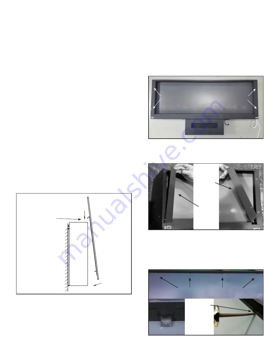
Secure with
Screw Here
Figure 3 Attaching Fireplace to Bracket
Faux Stone Installation
Arrange the white and clear faux stones along the inset
window ledge at the front of the firebox. Place clear
stones over LED bulbs and fill remaining gaps with white
stones.
Glass Front Installation
1. Remove Glass Front from appliance. Remove
two retaining screws that connect the mounting
brackets on the glass front to the top corners of
the appliance. Pull gently on the bottom of the glass
panel to disengage the plug connectors on the
bottom corners of the appliance. When the plug
connectors are disengaged, lift up on the glass front
to disengage the hanging brackets from the top
corners of the appliance. Set the glass front aside in
a safe location. See Figure 13.
2. Install glass front as shown in Figure 3. Engage tabs
on rear face of glass with the slots in the top of the
appliance. Install glass front so that the tabs on its
back side engage the slots in the top of the appli-
ance. Once both tabs engage, press firmly against
the bottom face of the glass panel to engage
the bottom connectors.
3. Secure the glass front to the appliance with two
screws (removed in step 1) through the two glass
front mounting brackets on the top of the appliance.
See Figure 3.
Figure 4 Bracket Screws
REMOVE SCREWS
REMOVE SCREWS
Screen Installation
1. Switch the main switch control on the right corner of
the appliance to the OFF position.
2. Unplug the power input cord from the wall receptacle.
3. Remove Glass Front. Refer to Glass Front Installa-
tion instructions.
4. Remove four screws, two screws on each side of the
appliance. See Figure 4.
6. Remove the side brackets on the appliance. See
Figure 5.
Right side
slides out
from under
the frame.
Left side lifts
up from the
frame.
Figure 5 Side Bracket Removal
7. Locate the four tabs at the top of the appliance frame
holding the screen into place.
8.
Using a flat screwdriver, lift tabs into an upright posit-
ion to release the screen. See Figure 6.
Lift Tabs (with
screwdriver
into an upright
position to
release the
screen.
TAB DETAIL
TABS SECURING SCREEN
Figure 6 Side Bracket Removal


