background image

11

SimpliFire  •  SF-WMS38-BK  •  2040-911 Rev. K  •  4/20


CAUTION! 

The unit’s power cord must be connected to 

a properly grounded and protected 120V outlet. Always 

use ground fault protection where required by the electri-

cal code.

WARNING! Risk of Electric Shock!  

Do not operate the 

unit if it is damaged or has malfunctioned.  If you suspect 

the unit is damaged, call a qualified service technician to 

inspect and replace any part of the electrical system if 

necessary.

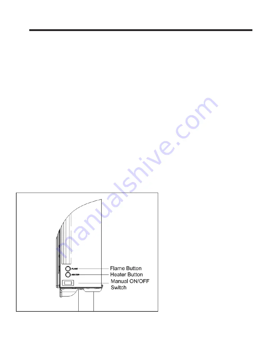
A.  Manual Switch Function

The appliance can be operated by both remote control 

and manual button.  Once the unit has been connected 

to a grounded electrical outlet, turn on the main power 

switch located on the right side of the appliance.  A beep 

should be heard when the power is first applied. See 

Figure 5.1.

Main Power Switch

The POWER switch supplies power to all functions of 

the appliance.  This switch must be in the “ON” position 

for any of the functions including the remote. 

Note

To use both remote and manual function, the main 

power switch must in “ON” position.

Flame Button

By pressing the FLAME button, the unit will cycle 

through four flame effects.  

Heater Button

-   Press the heater button once to turn 750W power on. 

  Appliance will beep and illuminate 1 red LED.

-   Press again turns 1500W power on. 

 Appliance will beep and illuminate 2 red LEDs.

-   Press third time turns heater off. 

Note:

  A harmless slight brief odor may occur during first 

use or after prolonged period of storage. 

Figure 5.1 Manual Operating Switches

OPERATING INSTRUCTIONS


Summary of Contents for SF-WM38-BK

Page 1: ...ALL OPERATE OR MAINTAIN THIS PRODUCT PROTECT YOURSELF AND OTHERS BY OBSERVING ALL SAFETY INFORMATION FAILURE TO COMPLY WITH INSTRUCTIONS COULD RESULT IN PERSONAL INJURY AND OR PROPERTY DAMAGE Congratu...

Page 2: ...foreign objects to enter any ventilation or exhaust opening as this may cause an electric shock or fire or damage the appliance To prevent a possible fire do not block appliance connection fan air int...

Page 3: ...specting Appliance 5 D Model and Serial Number Information 5 3 GETTING STARTED A Parts and Hardware 6 B Tools and Supplies Needed 6 C Appliance 6 D Location 7 E Clearance to Combustibles 7 F Electrica...

Page 4: ...ems or other external sources and residues left on the plated surfaces from the use of abrasive cleaners or polishes Repair or replacement of parts that are subject to normal wear and tear during the...

Page 5: ...all parts have been received Read all the instructions before starting the installation Follow these instructions carefully during the installation to ensure maximum safety and benefit D Model and Ser...

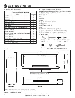
Page 6: ...Part Quantity Fire Box 1 Glass 1 Pedestal 1 Instruction Manual 1 Remote Control 1 AAA Battery 2 Wall Mounting Bracket attached to unit 1 Masonry Anchor 4 Screw ST5 x 40 4 Machine Screw M5x16 attached...

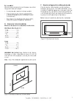
Page 7: ...6 in WARNING Risk of Fire Keep electrical cords drapery furnishings or other combustibles at least 3 ft 0 9 m from the front of the appliance and away from the sides or rear Note One of the installati...

Page 8: ...e Section B Masonry Wall In the marked locations drill four 5 16 in diameter x 2 in deep holes Insert the provided wall anchors into the holes Gently tap the anchors with a hammer until they are flush...

Page 9: ...ltimate values or less as required by building authorities Framed Wall For each of the marked mounting point locations determine which points align with a structural fram ing member At the points wher...

Page 10: ...rence Not all media need to be used F Glass Front Installation Install glass front by setting both hooks of the front glass panel into the slots at the top front edge of the firebox as shown in Figure...

Page 11: ...located on the right side of the appliance A beep should be heard when the power is first applied See Figure 5 1 Main Power Switch The POWER switch supplies power to all functions of the appliance Thi...

Page 12: ...ture set point Fireplace emits single audible beep to confirm command to transition to ON or STANDBY state FLAME By pressing the FLAME button the unit will cycle through four flame effects LCD illumin...

Page 13: ...ire To reduce risk of fire do not store or use gasoline or any other flammable vapors or liquids in the vicinity of the appliance WARNING Risk of Electrical Shock Any other servic ing needed must be p...

Page 14: ...number and serial number when requesting service parts from your dealer or distributor Stocked at Depot ITEM DESCRIPTION COMMENTS PART NUMBER 1 Black Glass GLA WM38 BK Y 2 Hardware Bag HRDW 38WM Y 3 H...

Reviews: