background image

7

SimpliFire  •  SF-WMS38-BK  •  2040-911 Rev. E  •  12/15


D.  Location

When choosing a location for your fireplace ensure that 

the general rules are followed:  

•  For best results, install out of direct sunlight.  

•  Power supply service must be installed within  

proximity of appliance prior to finishing to avoid 

reconstruction. 

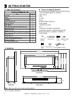
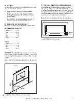
•  See Figure 3.1 for appliance dimensions and to 

determine location of appliance installation.

E.  Clearance to Combustibles 

Minimum Clearance to Combustible Construction

Wall Mount (See Figure 3.2) 


  Sides.......................0 in.
  Floor................13 3/4 in.
  Top..........................0 in.
  Back........................0 in.
  Front.....................36 in.
 

Stand  

  Sides.......................0 in.
  Top..........................0 in.
  Back........................0 in.
  Front.....................36 in.
 

WARNING! Risk of Fire! Keep electrical cords, drapery, 

furnishings or other combustibles at least 3 ft. (0.9 m) 

from the front of the appliance, and away from the sides 

or rear.

Note:  

One of the installation applications must be used. 

F.  Electrical Supply Circuit Requirements

Plan the location of the appliance so that it will have 

adequate electric power.  A 15 AMP, 120V/60hz. circuit 

is required.  Additional appliances on the same circuit as 

this appliance may exceed the current rating of that cir-

cuit.  A dedicated circuit is not required, but is preferred 

to prevent circuit breaker trips or fuse failure.

Note:  

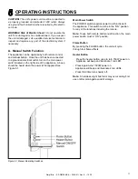
Access to electrical outlet must be maintained.

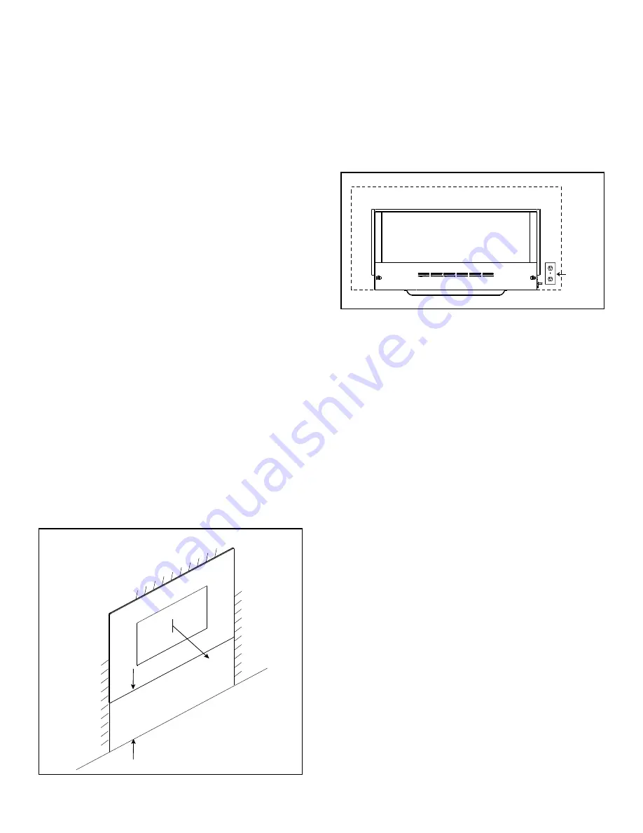
Figure 3.2  Wall Mount Clearance to Combustibles

ELECTRICAL

OUTLET

LOCATION

Figure 3.3 Electrical Outlet Location


FLOOR

W

AL

L

CEILING

13-3/4 in. min

   36 in. min

Summary of Contents for SF-WMS38-BK

Page 1: ...ALL OPERATE OR MAINTAIN THIS PRODUCT PROTECT YOURSELF AND OTHERS BY OBSERVING ALL SAFETY INFORMATION FAILURE TO COMPLY WITH INSTRUCTIONS COULD RESULT IN PERSONAL INJURY AND OR PROPERTY DAMAGE Congratu...

Page 2: ...foreign objects to enter any ventilation or exhaust opening as this may cause an electric shock or fire or damage the appliance To prevent a possible fire do not block appliance connection fan air int...

Page 3: ...g Appliance 5 C Model and Serial Number Information 5 3 GETTING STARTED A Parts and Hardware 6 B Tools and Supplies Needed 6 C Appliance 6 D Location 7 E Clearance to Combustibles 7 F Electrical Suppl...

Page 4: ...s or other external sources and residues left on the plated surfaces from the use of abrasive cleaners or polishes Repair or replacement of parts that are subject to normal wear and tear during the wa...

Page 5: ...he packaging Discard packaging Carefully inspect components for any damage Reference parts list to verify all parts have been received Read all the instructions before starting the installation Follow...

Page 6: ...Quantity Fire Box 1 Glass 1 Pedestal 1 Instruction Manual 1 Remote Control 1 AAA Battery 2 Wall Mounting Bracket attached to unit 1 Masonry Anchor 4 Screw ST5 x 40 4 Machine Screw M5x16 attached to p...

Page 7: ...WARNING Risk of Fire Keep electrical cords drapery furnishings or other combustibles at least 3 ft 0 9 m from the front of the appliance and away from the sides or rear Note One of the installation a...

Page 8: ...Section B Masonry Wall In the marked locations drill four 5 16 in diameter x 2 in deep holes Insert the provided wall anchors into the holes Gently tap the anchors with a hammer until they are flush...

Page 9: ...ltimate values or less as required by building authorities Framed Wall For each of the marked mounting point locations determine which points align with a structural fram ing member At the points wher...

Page 10: ...rence Not all media need to be used F Glass Front Installation Install glass front by setting both hooks of the front glass panel into the slots at the top front edge of the firebox as shown in Figure...

Page 11: ...h located on the right side of the appliance A beep should be heard when the power is first applied See Figure 5 1 Main Power Switch The POWER switch supplies power to all functions of the appliance T...

Page 12: ...ture set point Fireplace emits single audible beep to confirm command to transition to ON or STANDBY state FLAME By pressing the FLAME button the unit will cycle through four flame effects LCD illumin...

Page 13: ...Fire To reduce risk of fire do not store or use gasoline or any other flammable vapors or liquids in the vicinity of the appliance WARNING Risk of Electrical Shock Any other servic ing needed must be...

Page 14: ...equesting service parts from your dealer or distributor Stocked at Depot ITEM DESCRIPTION COMMENTS PART NUMBER 1 Black Glass GLA WM38 BK Y 2 Hardware Bag HRDW 38WM Y 3 Hanging Bracket BRACKET WM38 Y 4...

Reviews: