REV020620
SimpliPhi Power, Inc. | 3100 Camino Del Sol | Oxnard, CA 93030, USA | (805) 640-6700 |
| 26 |
5.
Charge Bank B fully, making sure all loads are disconnected at the time of initial charge
6.
Wire all Bank A batteries and Bank B batteries in parallel, adhering to the wiring methods outlined in
Section 4.3 above.
a.
Ensure that DC Positive common bus and DC Negative common bus ratings are appropriate
for the new larger quantity of batteries in the bank.
7.
Reprogram all inverter/charger and/or charge controller equipment for the new larger battery bank
capacity.
a.
New charging current parameters for the expanded bank should be appropriate for the
oldest included PHI battery model. For example, a battery bank composed of one PHI 3.5
battery with a maximum continuous charge rate of 34 Amps DC and one PHI 3.8 battery with
a maximum continuous charge rate of 37.5 Amps DC has a combined maximum continuous
charge rate of 68 Amps DC (
not
71.5 Amps DC).
5.0
–
Programming
5.1
–
Operating Parameters per Warranty
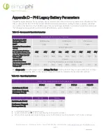
To maintain PHI Battery health and to comply with the Warranty, adhere to the operating parameters outlined in
Tables 4.0 and 5.0 below. Refer to the manufacturer-
specific Integration Guide from SimpliPhi’s Product
Documentation web page for a complete list of settings:
https://simpliphipower.com/product-documentation/.
Table 4.0
–
Warranty Operation Parameters
Recommended Operating Conditions for 10 Year Warranty
Equivalent to 80% Retained Capacity
10,000 cycles
5,000 cycles
3,500 cycles
Depth of Discharge (DoD)
80%
90%
100%
Operating Temperature °F (°C)
32 to 120 (0 to 49)
Programming Settings for Ancillary
Equipment
12V
24V
48V
12v
24V
48V
12V
24V
48V
Low Battery Cut-Off Voltage (V)
3
12.6
25.1
50.2
12.4
24.8
49.6
12
24
48
Absorb / High Cut-Off Voltage (V)
13.6
27.2
54.4
13.6
27.2
54.4
14
28
56
Absorb Time
2 Hours
Absorb End Amps (if applicable)
2% of the PHI Battery bank’s total Ah capacity
The charge cycle should be programmed to 2 Stage / No Float. Utilizing a Float Charge is permissible only in charge
controllers’ programming. Refer to the relevant Integration Guide for complete charge controller settings.


