background image

REV020620


SimpliPhi Power, Inc.  |  3100 Camino Del Sol  |  Oxnard, CA 93030, USA  |  (805) 640-6700  |  

info@simpliphipower.com

|  

SimpliPhiPower.com


|  17  |          


4.5 

 PHI Battery Connection Terminals 

4.5.1 

 Batteries with Threaded Studs


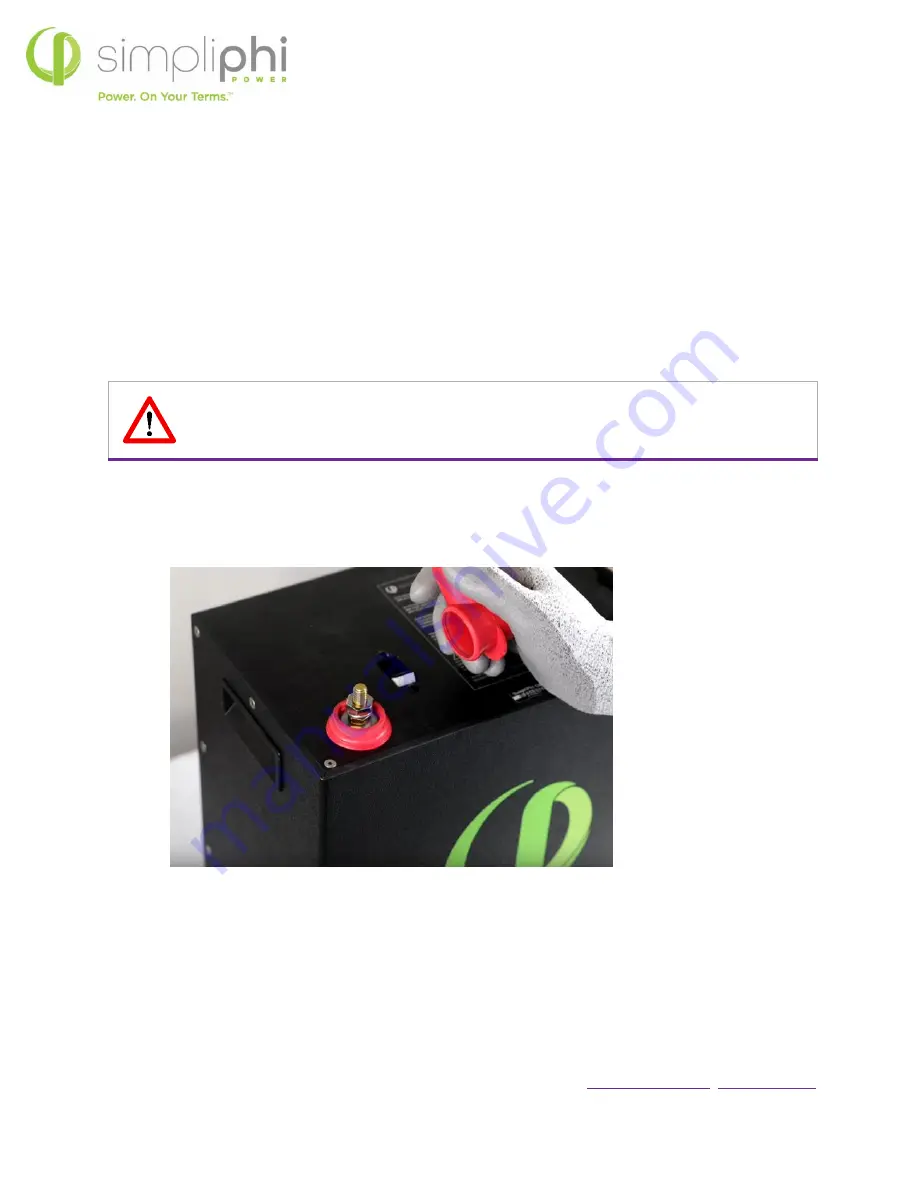
The largest PHI Battery sizes (such as the PHI 3.8 and PHI 2.9) are equipped with two 3/8’’ (10 mm) 

threaded studs with a lock washer and nut. The red colored high temperature molded insert connection is 
for the positive lead. The black colored high temperature insert connection is for the negative lead.  
 
Water Resistant Cable Boots are also included and will be in place when your units arrive. The boots are to 
be placed over the cable terminations and will stretch to form a water-resistant seal around the base of the 
molded inserts and terminal connections. 


CAUTION:  Do not attempt to loosen the large brass nut at the base of the terminals; doing so 
will damage the PHI battery and Void the Warranty. 

4.5.2 

 Torque Value for Batteries with Threaded Studs 

PHI Batteries with threaded stud terminals have a torque specification of 160 in-lbs. (13.3 ft-lbs.). 


Threaded Studs = 3/8” (10mm)


Torque Value = 160 in-lbs 

4.5.3 

Batteries with Anderson Connectors 

The smallest PHI Battery sizes (such as the PHI 1.4 and PHI 730) are equipped with SB 50 Anderson 
connectors utilizing P/N 5900 #6 HD contacts. 


12V connections are YELLOW 


24V connections are RED 


To avoid any spark or electrical event when connecting batteries with Anderson Connectors, turn the 
accompanying equipment off, connect cables with appropriate battery mating connectors to the equipment, 

Summary of Contents for PHI 1.4 Series

Page 1: ...SIMPLIPHI POWER INC REV020620...

Page 2: ...reduces operating temperature constraints toxic coolants and the risk of thermal runaway Safe lithium ferrous phosphate LFP No cobalt No toxic hazards SimpliPhi s battery technology utilizes the indu...

Page 3: ...4 2 Environmental Considerations 14 4 2 1 Charging at Temperatures Below Freezing 14 4 2 2 Explosive Gas Precautions 14 4 2 3 Anti Corrosion Protection 14 4 3 Mounting Hardware 14 4 4 Dimensions and...

Page 4: ...hi Technical Support at 805 640 6700 x 1 regarding the compatibility of any equipment not explicitly listed in the Integration Guides section of the Product Documentation web page https simpliphipower...

Page 5: ...impliPhi with any questions We are committed to working with you and your installation team to achieve a safe reliable storage system that will provide years of maintenance free service that is covere...

Page 6: ...breaker This breaker increases safety during shipping and installations and allows the battery to effectively be turned OFF or ON The breaker works in conjunction with the battery s built in BMS and c...

Page 7: ...4 Amps DC 358 4 W DC 28 5 Amps DC 364 8 W DC DC Voltage Range1 24 to 28 VDC 48 to 56 VDC 24 to 28 VDC 48 to 56 VDC 24 to 28 VDC 12 to 14 VDC 24 to 28 VDC 12 to 14 VDC Depth of Discharge1 up to 100 Ope...

Page 8: ...n page 4 of this Manual 2 2 Response to Emergency Situations As with any battery if the PHI Battery s cells are severely damaged due to physical abuse reverse polarity high voltage unmitigated current...

Page 9: ...y bank but also all other power related sizing parameters as outlined in Sections 3 2 1 3 2 2 or 3 2 3 and 3 2 4 Failure to do so will Void the Warranty CAUTION PHI Battery bank sizing not in accordan...

Page 10: ...ient to use the PHI 3 8 kWh 51 2Vnominal battery with 1 92 kW of maximum continuous discharge versus the PHI 3 8 kWh 25 6Vnominal battery with 1 15 kW of continuous discharge The same advantages apply...

Page 11: ...ystem including the solar power available for powering loads and for exporting to the grid Furthermore greatly reducing the PV array s output via the charge controllers effectively wastes the solar PV...

Page 12: ...arge assuming that the charge controllers full current output rating is utilized Failing to do so will destroy the PHI batteries and Void the Warranty 3 2 3 Sizing for Maximum Instantaneous Charge Rat...

Page 13: ...id the Warranty Note that this quantity of PHI Batteries is the minimum requirement to prevent over discharge and over charge from an instantaneous power perspective The system may need more PHI Batte...

Page 14: ...y confined space containing vented batteries or flammable chemicals such as natural gas NG liquid petroleum gas LPG or gasoline Benzine Petrol Do not install in a confined space with machinery powered...

Page 15: ...200 pounds each of downward pressure along the bracket s outer edge During this test a deflection of approximately 30 thousandths of an inch was measured Bracket sets are designed to hold one PHI 3 8...

Page 16: ...3 0 Specifications PHI 2 9 Battery PHI 2 9 Battery w Mounting Bracket PHI 2 9 Battery PHI 2 9 Battery w Mounting Bracket Width 11 25 13 7 15 5 with mounting flanges Height 12 75 including 1 75 termin...

Page 17: ...to form a water resistant seal around the base of the molded inserts and terminal connections CAUTION Do not attempt to loosen the large brass nut at the base of the terminals doing so will damage the...

Page 18: ...age Capacity and total available Amperage is increased incrementally with the number of units wired in Parallel For example two PHI 3 8 kWh 51 2Vnominal 75Ah Batteries wired in parallel are rated at a...

Page 19: ...n length and gauge in order to balance the load across all PHI Batteries in the installation CAUTION Identical wire lengths and identical wire gauges from each PHI Battery in a PHI Battery bank is a c...

Page 20: ...to include the 3 8 lugs that fit on the PHI Battery s threaded studs Determine the cable length for the PHI Battery terminal farthest from the common busbar or plate first Additional cabling or slack...

Page 21: ...s a washer should be placed between the current carrying terminal and the cable lug or interconnecting busbar Doing so will Void the Warranty CAUTION Spark may be present when connecting wires to PHI...

Page 22: ...ached to the batteries terminals Interconnecting busbars for paralleling either two SKU BB 2 or three SKU BB 3 PHI batteries with threaded studs are available from SimpliPhi at an additional cost CAUT...

Page 23: ...miliar with general electrical safety precautions and specific regional code requirements IfthePHIBattery s voltagehasdropped during anextended periodinstorage toa voltage belowtheinverter sminimum st...

Page 24: ...at the PHI Battery terminals will destroy the PHI batteries and Void the Warranty 7 ConfirmallloadsareturnedOFF Disconnecttheinverter sACOutputbreakerorturnoffthebreakeratthetop ofyourloads breakerpan...

Page 25: ...tery bank composed of two PHI 3 5 batteries and one PHI 3 8 battery has a total energy storage capacity for system sizing calculations of 10 5 kWh for the bank 3 X 3 5 kWh 10 5 kWh total In addition t...

Page 26: ...t 71 5 Amps DC 5 0 Programming 5 1 Operating Parameters per Warranty To maintain PHI Battery health and to comply with the Warranty adhere to the operating parameters outlined in Tables 4 0 and 5 0 be...

Page 27: ...d above the battery rests at approximately 13 3V 26 7V 53 3V Refer to Table 6 0 below for a complete Battery Voltage versus State of Charge SOC gauge Table 6 0 Battery Voltage VS State of Charge SOC a...

Page 28: ...r to turn on To measure a single battery s voltage within a battery bank only the battery being measured has its built in breaker in the ON I position all other batteries in the bank must have their b...

Page 29: ...cals contained in Lithium Ferro Phosphate cells electrolyte do not electrolyze to any appreciable extent within the PHI Battery s operating voltage range In contrast lead acid batteries which contain...

Page 30: ...Batteries are maintenance free as long as all the Installation Manual Integration Guidelines and Warranty requirements are adhered to B 2 4 Life Cycles PHI Batteries are designed for thousands of cycl...

Page 31: ...unlike NMC NCA LCO NiMH NiCad or Lead Acid types of batteries including AGM The PHI Batteries contain the least amount of toxic metals and are the most eco friendly of all common battery types Lithium...

Page 32: ...mum Battery Quantity PHI 2 9 51 2Vnom Minimum Battery Quantity Magnum MS 4448 4 4 94 4 7 3 4 Magnum MS 4048 4 94 4 3 3 3 OutBack Radian 8048A 8 93 8 6 5 6 OutBack Radian 4048A 4 93 4 3 3 3 OutBack Sky...

Page 33: ...3 3 4 8 Samlex EVO 4024 4 94 4 3 4 4 6 12 Samlex EVO 2224 2 2 93 2 4 3 3 4 7 Schneider SW 4024 4 92 4 3 4 4 6 13 Schneider SW 2524 2 5 91 5 2 7 3 3 4 8 Victron Quattro 24 5000 120 5 94 5 3 5 5 8 15 V...

Page 34: ...MidNite Solar Classic 200 24V system 78 2 2 3 6 MidNite Solar Classic 200 12V system 79 3 MidNite Solar Classic 250 48V system 55 2 2 2 2 2 4 2 2 MidNite Solar Classic 250 24V system 62 2 2 3 5 MidNi...

Page 35: ...Max Output ADC PHI 3 8 51 2V PHI 2 9 51 2V PHI 3 8 25 6V PHI 2 9 25 6V PHI 1 4 25 6V PHI 730 25 6V PHI 1 4 12 8V PHI 730 12 8V Sol Ark 12K includes dual MPPTs 185 5 7 5 5 7 14 5 7 Victron SmartSolar...

Page 36: ...ommended and available online for purchase at this link The 48V 30A for LiFePO4 LiFeYPO4 58 8V GMS charger from GWL Power is recommended and available for online purchase at this link The Smart Charge...

Page 37: ...ry Equipment 12V 24V 48V 12v 24V 48V 12V 24V 48V Absorb High Cut Off Voltage V 3 13 6 27 2 54 4 13 6 27 2 54 4 14 28 56 Absorb Time 2 Hours Absorb End Amps 2 of the PHI Battery bank s total Ah capacit...

Reviews: