REV020620
SimpliPhi Power, Inc. | 3100 Camino Del Sol | Oxnard, CA 93030, USA | (805) 640-6700 |
| 18 |
and then make final connections via connectors to the batteries bef
ore turning on the system’s
accompanying equipment.
4.6
–
Wiring
CAUTION: All PHI Batteries are designed to serve at fixed voltages and cannot be wired in
series to increase the battery bank’s voltage. Wiring the PHI Batteries in
series will result in
d
amage to the PHI Battery’s protective circuitry and will Void the Warranty. PHI batteries are
designed for parallel wiring only to increase the battery bank’s storage capacity.
4.6.1
–
Increasing Storage Capacity via Parallel Wiring
Storage Capacity and total available Amperage is increased incrementally with the number of units wired in
Parallel. For example, two PHI 3.8 kWh-51.2V
nominal
(75Ah) Batteries wired in parallel are rated at a
combined 7.6 total kWh, 51.2 Volts DC and 150Ah. Each PHI 3.8 kWh-51.2V
nominal
Battery also has a
maximum continuous discharge rate of 37.5 Amps DC and paralleling two of these batteries incrementally
increases the maximum continuous charge and discharge rate. The two paralleled PHI 3.8 kWh-51.2V
nominal
batteries have a combined maximum continuous charge and discharge rate of 75 Amps DC (2 × 37.5ADC).
4.6.2
–
Parallel Wiring Batteries with Threaded Studs using Battery Cables
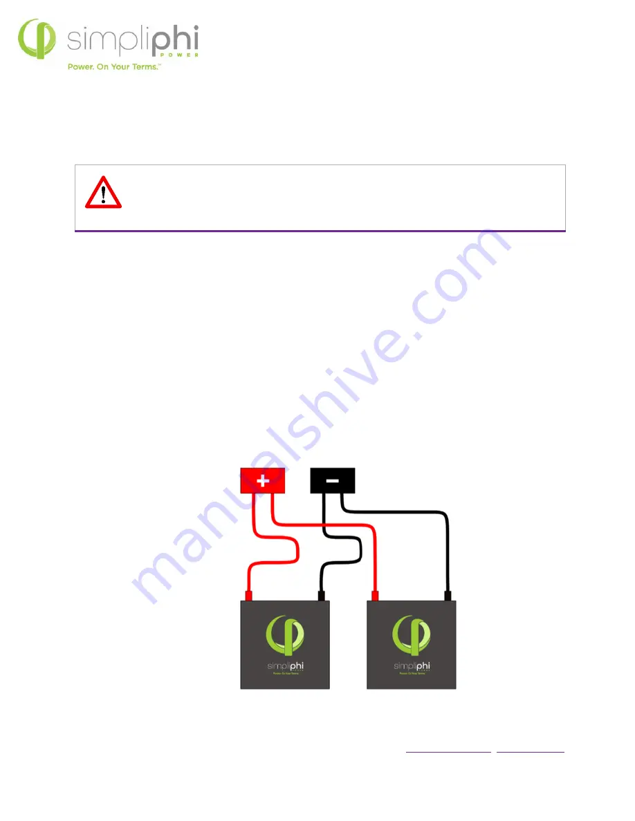
PHI Batteries are paralleled by wiring from individual PHI Batteries to DC busbars or plates, which may be
located in a DC combiner box or the inverter’s power panel.
Figure 4.0
–
Two PHI Batteries in Parallel


