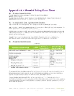
REV022618
SimpliPhi Power, Inc. | 420 Bryant Circle | Ojai, CA 93023, USA | (805) 640-6700 | info@simpliphipower.com |
SimpliPhiPower.com
| 13 |
partners, and to the community at large. Please be aware of the potential electrical hazards
before interacting with any and all electrical or mechanical devices. Please take all necessary
precautions in your projects and installations. Please refer to Section 1 for safety guidelines.
PHI 2.7 Batteries feature a Low Battery Voltage Cut Off (LBCO). This is a self-protection
mechanism that prevents over discharge. The LBCO will cause the PHI 2.7 Battery to turn off
once batteries approach Zero Capacity or 100% Depth of Discharge.
Most, if not all, inverters have related features. These features are often referred to as “Load
Disconnect”, “Load Shedding” or similar. These features are there to protect the PHI 2.7 Battery
bank from excessive discharge. In instances of low battery voltage, when there is no incoming
energy to recharge the PHI 2.7 Battery bank, the inverter will disconnect the load and remain in
standby until the PHI 2.7 Battery bank is recharged.
For off grid installations, where charge energy is only provided by renewable energy such as PV
arrays, Inverter “Load Disconnects” are generally set at a value that will allow a system to remain
online and in standby for at least 24 hours (10% at top of charge and 10% at bottom of charge).
This allows a system to stay online until at least one full day of sun can recharge the PHI 2.7
Battery bank.
In any application, off-grid or grid-tied, if your PHI 2.7 Battery bank is reaching the LBCO, load
disconnects or load shedding set points may need to be adjusted. Refer to Programming section.
In case of LBCO, cycle the DC Battery Disconnect (inverter), in order to reset the system. Only
complete this procedure when there is a charge source available, otherwise, the system will
simply reach LBCO in a short time period and shut down again.
5.0 – Programming
5.1 – Operating Parameters per Warranty
Although the PHI 2.7 Batteries are capable of performing at very high rates and depths of discharge
within a very wide temperature range, in order to achieve extended life cycles and to comply with the
Warranty, the operating parameters, indicated in Tables 3.0 and 4.0 below, must be adhered to.
Table 3.0 – Warranty Operation Parameters
Recommended Operating Conditions for 10 Year Warranty
Equivalent to 80% Retained Capacity
10,000 cycles
5,000 cycles
3,500 cycles
Discharge/Charge Rate
1,2
C/2
DoD
4
80%
90%
100%
Operating Temperature °F (°C)
32 to 110 (0 to 43)
32 to 120 (0 to 49)
32 to 120 (0 to 49)
Programming Settings for Ancillary
Equipment
24V
48V
24V
48V
24V
48V
Absorb / High Cut-Off Voltage (V)
3
28
56
28.8
57.6
28.8
57.6
Recharge / Low Cut-Off Voltage (V)
3
25.1
50.2
24.8
49.6
24
48

