background image

REV020918


SimpliPhi Power, Inc.  |  420 Bryant Circle  |  Ojai, CA 93023, USA  |  (805) 640-6700  |  info@simpliphipower.com  |  

SimpliPhiPower.com


|  4  |                                                              


Section 1.0 – PHI 3.5 Battery Safety Protocol


Section 1.1 – Safety & Protective Features 

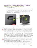
1.1.1 – 80A Breaker 

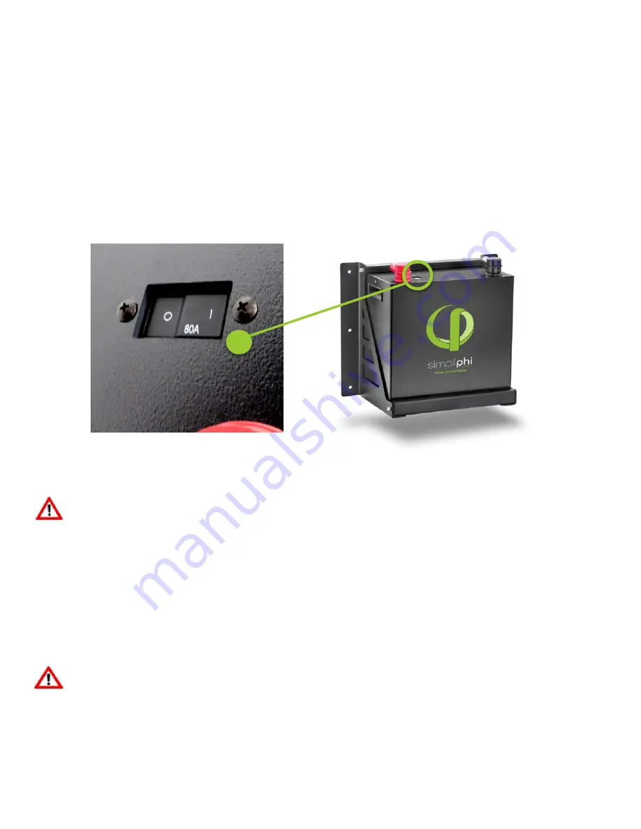
All PHI 3.5 Batteries are outfitted with an 80A hydraulic/magnetic circuit breaker which will show a 

white base when tripped. This breaker increases safety during shipping and installations and 

allows the battery to effectively be turned “off” or “on.” The breaker works in conjunction with the 

built-in battery management system (BMS) and creates additional safety, efficiency and 

functionality to the overall power storage system. 


Figure 1.0 - PHI 3.5 80A Circuit Breaker 


CAUTION: 

Circuit Breakers, Disconnects and Fuses should be employed throughout several points of a 

power storage and generation installation to effectively isolate and protect all components of the system 

to safeguard against faults, short circuits, polarity reversals or a failure of any component in the overall 

system. Fuses, breakers, wiring ratings and values should be determined by established standards and 

evaluated by certified electricians, licensed installers, and regional code authorities. Although each PHI 

3.5 Battery contains both an 80 Amp circuit breaker and an internal BMS with circuitry that protects the 

Lithium Ferrous Phosphate cells from overcharge, over-discharge and excessive load amperage, the PHI 

3.5 Batteries must always be installed with a charge controller and the appropriate settings to protect the 

PHI 3.5 from open PV voltage and other high voltage charging sources. The PHI 3.5 Battery Management 

System (BMS) and internal circuit breaker alone will not protect the PHI batteries from these extreme 

electrical phenomena. Failure to adhere to installation protocol will void the Warranty. 


CAUTION: 

Verify polarity at all connections with a standard volt meter before 1) energizing the system 

and 2) turning the PHI 3.5 80 Amp breaker “ON/OFF” switch to the “ON” position. 

Reverse polarity

 at the 

battery terminals will void the Warranty and destroy the batteries. 

PHI 3.5 Batteries pose some risk of shock or sparking during the installation and initial wiring and 

connection process. This is consistent with all other battery-based storage formats. Be sure to turn the 

built-in 80 Amp breaker to the “OFF” position to minimalize the risk of shock or sparks during the 

Summary of Contents for PHI 3.5

Page 1: ... 5TM Battery Optimized Energy Storage Management for Residential Commercial Applications Utilizing Efficient Safe Non Toxic Energy Dense Lithium Ferrous Phosphate LFP Chemistry SIMPLIPHI POWER INC REV020918 INSTALLATION MANUAL ...

Page 2: ... gain control of your own power SimpliPhi helps you manage your power as a personal resource Anytime Anywhere SimpliPhi energy storage optimizes integration of renewable power with the grid and protects your home and mission critical business functions from power outages and intermittency SimpliPhi storage technology eliminates operating temperature constraints toxic coolants and the risk of therm...

Page 3: ...cting Cable Leads to the PHI 3 5 Batteries 13 3 1 1 Considerations for Power Cable Terminals 3 1 2 Protection from the Environment 3 2 Final Connection of the Installation 13 Section 4 0 Operating Parameters Per Warranty 14 Section 5 0 PHI 3 5 Battery Safety Green Attributes Certifications 15 5 1 Safety Attributes and Certifications 15 5 1 1 Intrinsically Safe Operation Installation 5 1 2 No Safet...

Page 4: ...standards and evaluated by certified electricians licensed installers and regional code authorities Although each PHI 3 5 Battery contains both an 80 Amp circuit breaker and an internal BMS with circuitry that protects the Lithium Ferrous Phosphate cells from overcharge over discharge and excessive load amperage the PHI 3 5 Batteries must always be installed with a charge controller and the approp...

Page 5: ...gh cold temperatures do not harm PHI batteries attempts to charge at subfreezing temperatures can adversely affect SOH and cycle life and will void the Warranty If the battery must be charged below 32 F 0 degrees C the rate of charge must be at no more than 5 of the battery s rated capacity C 20 CAUTION Only use a SimpliPhi approved LFP charger if ancillary charging is required before installation...

Page 6: ...rrive The boots are to be placed over the cable terminations and will stretch to form a water resistant seal around the base of the molded inserts and terminal connections Section 1 2 Battery Performance Parameters and Sizing Calculations PHI 3 5 Batteries are designed to operate at a continuous C 2 rate across a large operating temperature range As long as the batteries are kept within this range...

Page 7: ...nes ensures that a system will not require any manual balancing processes CAUTION Do not combine PHI 3 5 Batteries with other brands or chemistries CAUTION Do not mix PHI 3 5 Batteries from different installations clients or job sites Section 2 2 System Configuration Basic Concepts Safe and reliable installation requires trained and certified technicians The following discussion of PHI Battery con...

Page 8: ...The following illustration shows two PHI 3 5 Batteries in Parallel For example assume that these are 24V Batteries Note the overall Voltage range is not changed The arrangement remains at 24 Volts the available AH capacity ability to provide 24 Volt power over time has also been doubled with the addition of a 2nd battery The available amperage from the system has been doubled The same configuratio...

Page 9: ...ength for the battery terminal farthest from the bus Make all Battery cables a matching length Additional cabling or slack that remains with the shorter distance runs can be coiled and secured with Zip Ties Wiring Methods 1 For 1 to 8 units Wire directly to inverter charge controller equipment 2 For 6 to 20 units Use a DC combiner or panelboard 3 For 20 units Connect the battery terminals directly...

Page 10: ...30 thousandths of an inch was measured Combined bracket sets can easily bear weights in excess of 400 pounds Bracket sets are designed to hold one PHI 3 5 Module with a weight of 77 5 pounds Section 2 5 Battery Weight PHI 3 5 Batteries weigh 77 5 pounds The Wall Mount Bracket Assemblies weigh 8 Pounds The SimpliPhi Power Mounting Brackets should be mounted into load bearing beams studs or solid ma...

Page 11: ...REV020918 SimpliPhi Power Inc 420 Bryant Circle Ojai CA 93023 USA 805 640 6700 info simpliphipower com SimpliPhiPower com 11 Figure 4 0 Mounting Bracket Assembly ...

Page 12: ...terminals can be found for these and other common wire gauges Your installer can source these 3 1 1 Considerations for Power Cable Terminations Please factor in the below information for power cable terminations PHI 3 5 Battery Mounting Stud Size 3 8 Power Cable Wire Gauge Generally anywhere from 6 AWG to 2 0 AWG or larger 3 1 2 Protection from the Environment Anticorrosive compounds or epoxies ar...

Page 13: ...ttery bank In any application off grid or grid tied if your PHI 3 5 battery bank is reaching the LBCO load disconnects or load shedding set points may need to be adjusted Refer to Operating Parameters per Warranty In case of LBCO cycle the DC Battery Disconnect inverter in order to reset the system Only complete this procedure when there is a charge source available otherwise the system will simpl...

Page 14: ...neral reference only CAUTION All SimpliPhi Power products are designed to work exclusively in parallel Never connect in series to achieve higher voltages Section 5 0 PHI 3 5 Battery Safety Green Attributes Certifications This section covers the PHI 3 5 battery safety attributes and certifications such as the lack of thermal runaway and off gassing UN DOT certification and UL compliance It also cov...

Page 15: ...tion testing 5 1 5 UL Compliance The Lithium Ferrous Phosphate cells within the PHI 3 5 Batteries fully comply with the safety testing parameters of UL 1642 5 1 5 RoHS Compliant SimpliPhi Power Batteries are RoHS compliant Any RoHS compliant component is tested for the presence of Lead Pb Cadmium Cd Mercury Hg Hexavalent chromium Hex Cr Polybrominated biphenyls PBB and Polybrominated diphenyl ethe...

Page 16: ... phosphate chemistries being considered for large format batteries SimpliPhi Power believes that batteries based on our proprietary lithium ferrous phosphate chemistry and circuitry offer a clear advantage not only over alternate Li ion chemistries lithium cobalt oxide but all battery chemistries that are currently commercially available This belief is based on the minimal environmental impact ass...

Page 17: ...ion of a Manufactured Article and is not subject to the regulations of the Hazardous Products Act A 3 Hazards Identification Common Chemical Name CAS Percent of Content Classification Hazard Labeling Lithium Ferrous Phosphate LiFePo4 15365 14 7 25 35 Eye Skin Respiratory Irritant Carbon as Graphite 7440 44 0 12 18 Eye Skin Respiratory Irritant Aluminum Metal 7429 90 5 3 7 Inert Copper Metal 7440 5...

Page 18: ...e eye Medical Conditions Aggravated by Exposure Not Available A 4 First Aid Measures Skin Contact Wash affected area with lukewarm water for at least 30 minutes If irritation or pain persists seek medical attention Eye Contact Wash affected eye with lukewarm water for at least 30 minutes Rinse with saline solution if possible Seek medical attention Inhalation Move victim to fresh air and remove so...

Reviews: