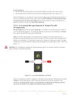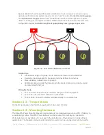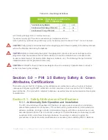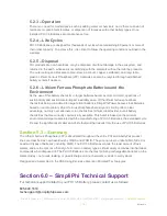
REV020918
SimpliPhi Power, Inc. | 420 Bryant Circle | Ojai, CA 93023, USA | (805) 640-6700 | info@simpliphipower.com |
SimpliPhiPower.com
| 6 |
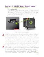
1.1.4 – PHI 3.5 Battery Connection Terminals
The PHI 3.5 Batteries are equipped with two 3/8’’ threaded studs with a lock washer and nut. The
red colored high temperature molded insert connection is for the positive lead. The black colored
high temperature insert connection is for the negative lead.
CAUTION:
Do not attempt to loosen the large brass nut at the base of the terminals.
CAUTION:
Do not reverse polarity. It will void the warranty. Use a volt meter to check polarity before connecting
terminals.
Water Resistant Cable Boots are also included and will be in place when your units arrive. The
boots are to be placed over the cable terminations and will stretch to form a water-resistant seal
around the base of the molded inserts and terminal connections.
Section 1.2 – Battery Performance Parameters and Sizing
Calculations
PHI 3.5 Batteries are designed to operate at a continuous C/2 rate across a large operating temperature
range. As long as the batteries are kept within this range during operation, then there is no need to de-
rate performance or increase sizing to compensate for the temperature. When used as recommended, no
increase in sizing, no special compensations or insulation needs to be considered when determining the
size of the energy storage and management system. See specific inverter manufacturer program settings
for optimizing system integration.
Table 1.0 - PHI 3.5 Specifications
Notes:
1. Max operating conditions. Refer to "Guide for Operating Parameters per Warranty" section.

