REV110619
SimpliPhi Power, Inc. | 3100 Camino Del Sol | Oxnard, CA 93030, USA | (805) 640-6700 | info@simpliphipower.com |
SimpliPhiPower.com
| 32 |
4.5.5
– Limiter Sensor Wiring Connections
The Sol-Ark AccESS installation may include limiter sensors. Limiter sensors are required in the following
applications:
•
Limited to Home mode
•
Time of Use Selling mode
•
Systems that include both a generator and grid connection
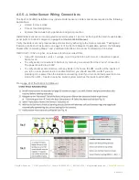
Install limiter sensors on incoming electrical service wires L1 and L2, at the top of the main house breaker
panel (refer to Sol-
Ark’s diagram on page 11 of the Sol-Ark-8K Manual).
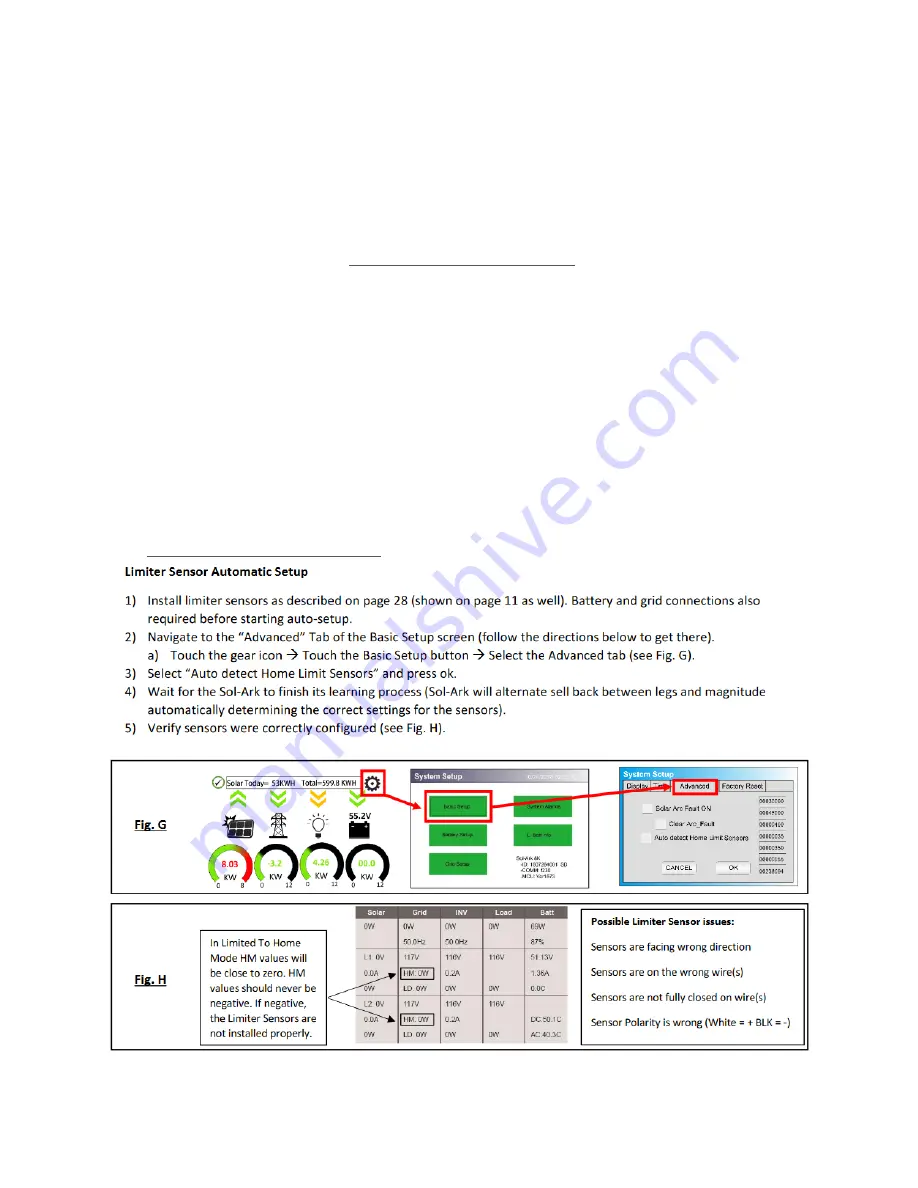
Verify the limiter sensors’ proper sense and direction by adhering to the Sol-Ark manual’s “Testing and
Powering Up Sol-
Ark” instructions on page 14 of the Sol-Ark Manual. If applicable, perform the following
checks
after
completing Steps 1 and 2 outlined in the Basic Functional Test Section 4.5.6 below:
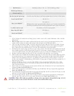
If MCU SW = 1654 or higher, an auto learn function avoids all this.
•
Using AC multi-meter, verify L1 voltage on AC in/out is 0Vac with main L1 connection in panel.
Same for L2.
•
To verify sensor connections to Sol-Ark, try removing one sensor from the main L1 connection.
The power should drop to 0W.
•
To verify proper sensor direction, with any loads in the home, the HM: +watts will be positive. If
you turn on solar panels and turn enable Grid Sell, you should see HM: -watts if you are
producing more power than the loads are consuming. And if you turn on limited power to Home
mode, then HM: ~0 watts to zero the meter (system matches the loads to within 99%).
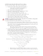
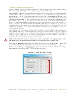
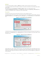
From page 26 of the Sol-Ark-12K Manual:


