REV110619
SimpliPhi Power, Inc. | 3100 Camino Del Sol | Oxnard, CA 93030, USA | (805) 640-6700 | info@simpliphipower.com |
SimpliPhiPower.com
| 33 |
4.5.6
– Basic Functional Test
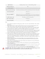
The following procedure should be followed once the installation is complete and before it is put into service.
Step 1: Confirm All Connections
After the AC and DC wiring has been installed and connected, check that all connections are correct and
secure.
Step 2: Apply Battery Power to the Inverter
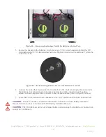
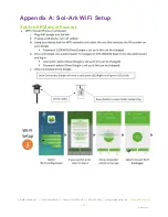
1. Measure the voltage and check polarity at all battery connection points. Measure the entire PHI
battery bank’s voltage and polarity on the Sol-Ark’s DC Positive and DC Negative connection
points, outlined in Figure 18.0 below.
Note: The Sol-Ark does not include a DC Disconnect breaker; a 225A fuse is included within the
Sol-Ark instead.
Figure 18.0
– Inverter & DC Power Supply ON/OFF Button
2.
Supply DC power to the Sol-Ark inverter by turning ON the ON/OFF button on the front of the
Sol-Ark unit. The inverter will power up and the inverter display panel will turn on.
Step 3: Verify Inverter Programming
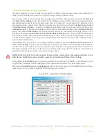
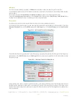
Although the AccESS Sol-Ark is pre-programmed to the correct battery charging parameters, the Sol-Ark
equipment offers different functionality based on
various other settings. Refer to this Manual’s
Programming section 5.0 for more information.
Step 4: Apply DC and AC Power to the Inverter
Turn all relevant DC and AC disconnects ON. When first commissioning the system, leave the Sol-
Ark’s
Load Output breaker OFF, and all circuits in the main house breaker panel OFF (if the Sol-Ark is
programmed to a mode of operation in which the batteries discharge to the main house breaker panel;
refer to Section 5.3 of this Manual for more information on the Sol-
Ark’s modes).
ON/OFF Button
(DC Power Supply)
Check DC
Voltage &
Polarity prior
to turning ON

