background image

REV110619


SimpliPhi Power, Inc.  |  3100 Camino Del Sol  |  Oxnard, CA 93030, USA  |  (805) 640-6700  |  info@simpliphipower.com  |  

SimpliPhiPower.com


|  44  | 

In an AC Coupled system setup that includes a generator, using a transfer switch for a grid-or-generator 
connection to the Sol-

Ark’s Grid Input also frees up the Sol-Ark Generator Input for connection to the AC 

Coupled solar PV array. 


If the system includes both a generator and a grid connection, limiter sensors are required. While smaller 
generators (less than 10 kW) can be wired to the Sol-

Ark’s Generator Input, Sol-Ark recommends wiring 

larger generators to a whole home transfer switch instead of using the inverter’s Generator Input. 

Smart Load 

The Smart Load feature allows the homeowner to run higher power non-essential appliances (hot water, 
dehumidifier, heat pump, irrigation pump, etc.) on solar when excess solar power is available. This setup 
involves connecting these higher power non-essential loads to the Sol-

Ark’s Generator Input. To partially 

protect  the  batteries  against  over-discharge,  set  the 

Smart  Load  Off  Batt

  and 

Smart  Load  ON  Batt


parameters to the batteries’ acceptable SoC percentage range while in this mode. However, note that no 
programmable parameter exists to regulate the batteries’ over-discharge from a 

current

 perspective.  

For example, an off-grid system with home loads totaling a maximum instantaneous power draw of 8 kW 
might include 5 PHI 3.8 batteries, with a maximum combined continuous power output of 9.6 kW

DC

 / 9.168 

kW

AC

.  With  both  the 

Smart  Load 

and

  Limited  to  Load 

modes  enabled  and  the 

Smart  Load  ON  Batt


parameter set to 100% SoC, the Sol-Ark will begin powering the Smart Loads (in addition to all the home 
loads)  when  the  batteries  are  at  100%  SoC.  If  the  Smart  Load  power  draw  exceeds  9.168  kW

AC

,  (38.2 

Amps  at  240VAC),  the  batteries  will  then  be  operating  beyond  their  maximum  continuous  power  output 
capabilities. While the batteries have a maximum surge discharge capability of 60 Amps DC per battery 
(15.36 kW

DC

 / 14.669 kW

AC

 for the 5-battery bank), the batteries cannot surge at this power level for more 

than 10 minutes. A Smart Load drawing more than 9.168 kW

AC

 for more than 10 minutes will very likely 

result in the batteries’ SoC level reaching the 

Smart Load OFF Batt

 parameter, if it is set to 95%. However, 

feel free to reach out SimpliPhi Power Technical Support (TechSupport@SimpliPhiPower.com) if the Smart 
Load feature will be used and battery bank sizing clarification according to Smart Load-specific loads needs 
to be clarified. 

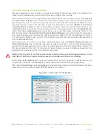
Note that in a grid-connected system that utilizes the 

Smart Load

 feature, the Wattage value to the right of 

the 

Smart Load ON Batt

 parameter in the 

Smart Load 

menu tab (see Figure 5) represents the minimum 

power required of the solar PV array before the Smart Loads are powered. Therefore, that Solar PV Wattage 
value  can  be  added  to  the  battery  bank’s  maximum  output  power  rating  when  comparing  maximum 
available solar and battery power available, against the Smart Load power draw:


𝑆𝑚𝑎𝑟𝑡 𝐿𝑜𝑎𝑑 𝐷𝑟𝑎𝑤 (𝑘𝑊) ≤

𝑆𝑜𝑙𝑎𝑟 𝑃𝑉 (𝑘𝑊) + 𝐵𝑎𝑡𝑡𝑡𝑒𝑟𝑦 𝐵𝑎𝑛𝑘 𝑀𝐴𝑋 𝑂𝑢𝑡𝑝𝑢𝑡 𝑃𝑜𝑤𝑒𝑟 (𝑘𝑊)

.


CAUTION: 

Smart Loads’ maximum power draw cannot exceed the Generator Input breaker’s 40 

Amp / 240VAC rating.


6.0 

– SimpliPhi Technical Support 

For technical support related to your AccESS, please contact us as follows: 

 
805.640.6700


techsupport@simpliphipower.com 


Summary of Contents for Sol-Ark AccESS

Page 1: ...ccESS INSTALLATION MANUAL Optimized Energy Storage Management for Residential Commercial Applications Utilizing Efficient Safe Non Toxic Energy Dense Lithium Ferrous Phosphate LFP Chemistry SIMPLIPHI...

Page 2: ...own power SimpliPhi Power helps you manage your power as a personal resource Anytime Anywhere SimpliPhi energy storage optimizes integration of any power generation source solar wind generator on or...

Page 3: ...Parameters and 12 Sizing Calculations 12 3 2 System Sizing for Your Installation 12 3 3 Installation Tools and Materials 13 3 4 Installation Site Location 13 3 5 Clearance Requirements 14 3 6 Knock O...

Page 4: ...l BMS with circuitry that protects the PHI 3 8 battery cells from overcharge over discharge and excessive load amperage the PHI batteries must always be installed with appropriate Balance of System eq...

Page 5: ...r storage system Figure 1 0 PHI 3 8 kWh 51 2Vnom 80A Circuit Breaker CAUTION Circuit Breakers Disconnects and Fuses should be employed throughout several points of a power storage and generation insta...

Page 6: ...l void the Warranty If the PHI 3 8 battery must be charged below 32 F 0 C the rate of charge must be at no more than 5 of the PHI 3 8 battery s rated capacity C 20 CAUTION Only use a SimpliPhi approve...

Page 7: ...Sol Ark equipment built into the SimpliPhi Power AccESS is not intended for use in connection with life support systems or other medical equipment or devices 1 4 Explosive Gas Precautions This equipm...

Page 8: ...0 C to 50 C Mounting Free standing or Pad mounted Enclosure Warranty Period 2 years Certifications UL1741SA Rule 21 HECO Rule 14H PREPA approved and Rapid Shutdown compliant Included batteries ETL cer...

Page 9: ...ination 3 kW AC 10 kW DC 3 kW AC 12 kW DC Good Combined Input Combination 4 kW AC 9 kW DC 4 kW AC 11 kW DC OK Combined Input Combination 5 7 kW AC 8 6 kW DC 2 kW AC 11 kW DC 5 7 6 kW AC 9 7 kW DC 1 kW...

Page 10: ...our PHI 3 8 kWh modules combined in parallel for a total energy storage capacity of 15 2 kWh 12 16 usable kWh at 80 DOD The AccESS Sol Ark 12K 22 8 kWh includes six PHI 3 8 kWh modules in parallel for...

Page 11: ...nit 2 3 1 AccESS Core Components The core components within the AccESS unit include the below listed products See Figures 2 0 3 0 for detail Sol Ark 8K manual linked here or Sol Ark 12K manual linked...

Page 12: ...I 3 8 batteries are operated at 80 maximum Depth of Discharge DOD The AccESS comes pre programmed for 80 DOD Please contact SimpliPhi Power Technical Support if alternative settings are desired Please...

Page 13: ...r AC DC Clamp On Current Meter Wire Stripper Impact Driver Masonry Bolts 3 4 Installation Site Location The AccESS may be installed indoors such as a garage or outdoors mounted onto a concrete pad The...

Page 14: ...cESS should be installed with 3 inch 7 62 cm clearance to the sides and 3 feet 0 91 m clearance to the front to allow for the cabinet door to be opened during installation Please see Figure 4 0 for de...

Page 15: ...tempt to wall mount the AccESS unit will void the Warranty 3 7 2 Pad Mounting the SimpliPhi AccESS Six 1 inch knockouts are located in the base of the AccESS for tool accessibility when mounting the A...

Page 16: ...REV110619 SimpliPhi Power Inc 3100 Camino Del Sol Oxnard CA 93030 USA 805 640 6700 info simpliphipower com SimpliPhiPower com 16 Figure 6 0 AccESS Unit Knockouts Bottom...

Page 17: ...el Any distance is permissible between the AccESS Sol Ark and the Essential Loads panel or Sol Ark transfer switch kit provided wire sizing and voltage drop is in accordance with local codes Figure 7...

Page 18: ...e you or your installer to contact us with any specific questions for technical support We are committed to working with you and your installation team to achieve a safe reliable storage system that w...

Page 19: ...6 Connect the cables that are pre wired into the Sol Ark to the interconnecting busbars secured to the batteries All connections are in parallel each positive cable connects to each positive busbar a...

Page 20: ...bottom of the cabinet and arrange three PHI 3 8 batteries on the AccESS s internal shelf Orient the modules so that the battery terminals point toward the AccESS door with the negative posts nearest t...

Page 21: ...anual CAUTION PHI 3 8 Batteries must be fully charged before commissioning the AccESS unit i e before connecting loads for the first time Failure to do so will void the Warranty CAUTION SimpliPhi does...

Page 22: ...ower com 22 4 5 Wiring the AccESS 4 5 1 Wiring Diagrams Please reference the below listed DC coupling and AC coupling diagrams where applicable DC Coupled System Figure 12 0 DC Coupled AccESS Sol Ark...

Page 23: ...0 info simpliphipower com SimpliPhiPower com 23 AC Coupled System Figure 13 0 AC Coupled AccESS Sol Ark Wiring Diagram To Batteries 5 Point Terminal Busbar NEG To Batteries 5 Point Terminal Busbar POS...

Page 24: ...i directional Generator Port 40A double pole breaker Load Output AC Out 50A double pole breaker Figure 14 0 below shows the Grid Generator and Load connection locations Also highlighted are the neutra...

Page 25: ...transfer switch is necessary to incorporate a generator into the system Figure 15 0 Generator Wiring in Grid Connected AC Coupled Systems It is also acceptable but not required to use a whole home ge...

Page 26: ...ode of operation so even in invert back up mode the inverter load sub panel neutral is bonded to ground by the utility grid system It must not be grounded again in the inverter s load sub panel System...

Page 27: ...des 3 Strip 0 5 of insulation from the PV conductors and insert into the appropriate charge controller port Figure 17 0 PV Array Connection Points DC Coupled Systems 4 Ground the solar PV array by pan...

Page 28: ...e Sol Ark s built in charge controllers 1 Due to the charge controller s starting voltage of 175VDC calculate the minimum number of solar panel modules needed to meet this target voltage at the module...

Page 29: ...r Based on calculations 2 and 3 above a maximum two parallel strings of eleven KuPower 300W modules in series can be wired to each of the Sol Ark 8K s two charge controllers 4 The charge controller ca...

Page 30: ...minimum number of solar panel modules needed to meet this target voltage at the module s maximum power voltage VMP In this example consider the Canadian Solar KuPower CS3K 300 solar PV module with a...

Page 31: ...f 9 24A equates to 27 72A at STC above the charge controller s operating current input limit of 20A Whereas two solar PV strings in parallel at the KuPower 300W module s IMP rating of 9 24A equates to...

Page 32: ...owering Up Sol Ark instructions on page 14 of the Sol Ark Manual If applicable perform the following checks after completing Steps 1 and 2 outlined in the Basic Functional Test Section 4 5 6 below If...

Page 33: ...18 0 Inverter DC Power Supply ON OFF Button 2 Supply DC power to the Sol Ark inverter by turning ON the ON OFF button on the front of the Sol Ark unit The inverter will power up and the inverter disp...

Page 34: ...ng source turn on the PV disconnect and wait until the PHI battery bank has had a chance to charge fully via solar power before turning on any loads For DC Coupled systems the solar PV array s ON OFF...

Page 35: ...utlined in this Operating Parameters section of this Manual If a firmware update is executed on the AccESS please verify all PHI custom settings are still in place 5 2 Operating Parameters Per Warrant...

Page 36: ...BMS Lithium Batt do not check this box Activate Battery do not check this box Charge Tab 80 DoD 90 DoD 100 DoD Start V Use Start instead of Start V when using Batt Charged instead of Batt V Charged in...

Page 37: ...ng source Programming the A value to the maximum value versus the reduced stress value does not impact the PHI Battery Warranty 5 By default battery charging from the solar PV array is prioritized ove...

Page 38: ...maximum amount of power pulled from the batteries and should be set to the PHI battery bank s maximum discharge rate in AC Watts To calculate the connected PHI battery bank s maximum discharge Watts...

Page 39: ...grid Net Energy Metering agreement required set the numerical value to the maximum number of exporting Watts Limited Power to Home check this box when powering both the essential loads sub panel and...

Page 40: ...double pole breaker and the For Micro inverter input box in the Smart Load tab of the Battery Setup menu must be checked Figure 22 0 Smart Load Tab in Batt Setup Menu The Sol Ark 8K is limited to a ma...

Page 41: ...ads from solar PV first if available then 2 grid 3 generator and 4 batteries To prioritize the batteries use over the grid or generator during specific set times also use the Time of Use Selling mode...

Page 42: ...ion of this Guide for battery bank sizing when batteries power the essential loads sub panel only Refer to the Discharge Example in Section 3 of this Guide for battery bank sizing when the batteries p...

Page 43: ...ire automatic switch The Sol Ark s Grid Input breaker can be used as the generator s input breaker In this scenario check the General Standard box and the GEN connect to Grid input box in the Grid Par...

Page 44: ...ited to Load modes enabled and the Smart Load ON Batt parameter set to 100 SoC the Sol Ark will begin powering the Smart Loads in addition to all the home loads when the batteries are at 100 SoC If th...

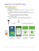
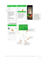
Page 45: ...REV110619 SimpliPhi Power Inc 3100 Camino Del Sol Oxnard CA 93030 USA 805 640 6700 info simpliphipower com SimpliPhiPower com 45 Appendix A Sol Ark WiFi Setup Sol Ark 8K Manual Excerpt...

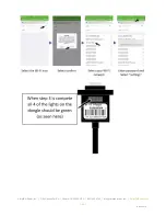
Page 46: ...REV110619 SimpliPhi Power Inc 3100 Camino Del Sol Oxnard CA 93030 USA 805 640 6700 info simpliphipower com SimpliPhiPower com 46...

Page 47: ...REV110619 SimpliPhi Power Inc 3100 Camino Del Sol Oxnard CA 93030 USA 805 640 6700 info simpliphipower com SimpliPhiPower com 47...

Page 48: ...REV110619 SimpliPhi Power Inc 3100 Camino Del Sol Oxnard CA 93030 USA 805 640 6700 info simpliphipower com SimpliPhiPower com 48...

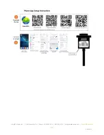
Page 49: ...nc 3100 Camino Del Sol Oxnard CA 93030 USA 805 640 6700 info simpliphipower com SimpliPhiPower com 49 Sol Ark 12K Manual Excerpt pg 19 22 iPhone https apps apple com us app powerview es id1460941008 A...

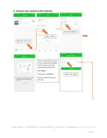
Page 50: ...REV110619 SimpliPhi Power Inc 3100 Camino Del Sol Oxnard CA 93030 USA 805 640 6700 info simpliphipower com SimpliPhiPower com 50...

Page 51: ...REV110619 SimpliPhi Power Inc 3100 Camino Del Sol Oxnard CA 93030 USA 805 640 6700 info simpliphipower com SimpliPhiPower com 51...

Page 52: ...REV110619 SimpliPhi Power Inc 3100 Camino Del Sol Oxnard CA 93030 USA 805 640 6700 info simpliphipower com SimpliPhiPower com 52...

Page 53: ...REV110619 SimpliPhi Power Inc 3100 Camino Del Sol Oxnard CA 93030 USA 805 640 6700 info simpliphipower com SimpliPhiPower com 53...

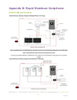
Page 54: ...REV110619 SimpliPhi Power Inc 3100 Camino Del Sol Oxnard CA 93030 USA 805 640 6700 info simpliphipower com SimpliPhiPower com 54 Appendix B Rapid Shutdown Compliance Sol Ark Manual Excerpt...

Page 55: ...REV110619 SimpliPhi Power Inc 3100 Camino Del Sol Oxnard CA 93030 USA 805 640 6700 info simpliphipower com SimpliPhiPower com 55...

Reviews: