background image

13

refer to the equipment manual and its specific warnings and instructions, and
observe them as well as those contained herein.

1.

The 14510-2 should only be used by personnel qualified to recognize
shock hazards and trained in the safety precautions required to avoid
possible injury.

2.

Do not connect any terminal of this Instrument to a circuit point at which a
voltage exceeding 600 volts AC or DC may exist with respect to earth
ground. (Refer to Table 1-3, item 12.)

3.

This Instrument is intended only for use indoors or in sheltered locations.
To prevent fire or shock hazards, do not expose it to rain or moisture.
Condensation may occur when the Instrument is moved from a cold area
to a warm area. DO NOT ATTEMPT HIGH VOLTAGE MEASUREMENTS
UNTIL CERTAIN THAT THE INSTRUMENT HAS DRIED THOROUGHLY.

4.

Turn off power and discharge any capacitors in the circuit to be mea-
sured before connecting to or disconnecting from it.

5.

Before using this Instrument, check accessories (if any) and test leads
for missing, damaged, deteriorated or otherwise faulty insulating parts.
Do not use, or permit the use of, equipment with faulty insulation until it
has been properly repaired.

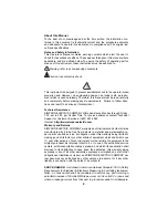
IMPORTANT:
6.

Always wear safety glasses when working with electrical circuitry.

7.

Do not work alone on high voltage circuits. Make certain that someone
capable of rendering aid is nearby and aware.

8.

Do not handle the Instrument, its test leads or the circuitry while taking
any measurements.

9.

Be sure to reset the range switch to the OFF position after completing
resistance or current measurements. This is to prevent inadvertent appli-
cation of high voltage to the resistance or current ranges when the In-
strument is next used.

10. Hands, shoes, floor and workbench must be dry. Avoid measurements

under humid, damp or other environmental conditions that could affect
the dielectric withstanding voltage of the test leads of the Instrument.

11. Do not change switch settings or test lead connectionswhile the circuit is

energized. A mistake could result in damage to the Instrument and pos-
sible personal injury.

12. Locate all voltage sources and accessible current paths before making

connections to circuitry.

NOTE:  Voltage may appear unexpectedly or in unexpected locations in faulty
equipment. An open bleeder resistor, for example, may result in a capacitor
retaining a dangerous charge.

13. Make certain that the equipment being worked upon is properly grounded

and fuses are of the proper type and rating.

14. Check and double check switch positions and jack connections before

applying power to the Instrument.

15. Always remain alert for low voltage circuits which may be floating at high

voltage with respect to earth ground and for composite voltages (AC +
DC) such as are found in rf amplifiers. The floating voltage or composite

Summary of Contents for 14510-2

Page 1: ...Simpson 14510 2 Volt Ohm Milliammeter OPERATOR S MANUAL...

Page 2: ...rt or Customer Service at 847 697 2260 Internet http www simpsonelectric com Warranty and Returns SIMPSON ELECTRIC COMPANY warrants each instrument and other articles manufactured by it to be free fro...

Page 3: ...nt equipment or general laboratory applications Some high power circuits however are within its measurement range and present an arcing explosion hazard in the event of an unanticipated circuit behavi...

Page 4: ...4 NOTES...

Page 5: ...5 NOTES...

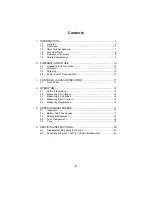
Page 6: ...ts 10 3 CONTROLS JACKS AND INDICATOR 11 3 1 Front Panel 11 4 OPERATION 12 4 1 Safety Precautions 12 4 2 Measuring DC Voltages 14 4 3 Measuring AC Voltages 14 4 4 Measuring Direct Current 15 4 5 Measur...

Page 7: ...n either a vertical or horizontal position The horizontal position is preferred for greater accuracy since the Instrument is calibrated in that posi tion 1 3 Items And Accessories All applicable items...

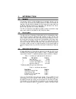
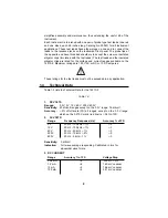
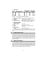
Page 8: ...atings are 100 V AC or DC or 10 DC amperes These ratings for the test leads must not be exceeded in any application 1 4 Technical Data Table 1 3 lists the Technical Data for the 14510 2 Table 1 3 1 DC...

Page 9: ...sly be applied to the circuits of an instru ment 1 5 Definition Of Accuracy The voltage and current accuracy of the Instrument is commonly expressed as a percent of full scale This should not be confu...

Page 10: ...ligator clips for the test leads are in a polyethylene bag See Section 5 for instructions on how to open the battery compartment and install the bat teries 2 2 Warranty The Simpson Electric Company wa...

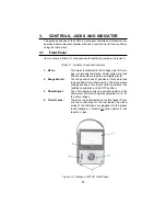
Page 11: ...hile others require a multiplying factor 2 Range Switch The range switch has 21 positions It may be turned to any position from either direction There are eleven voltage positions four direct current...

Page 12: ...y be attached to the probe tips Eliminating the need to hand hold test probes to a circuit for extended periods the test clips also reduce hand prox imity to a high voltage circuit while energized Cir...

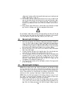
Page 13: ...certain that someone capable of rendering aid is nearby and aware 8 Do not handle the Instrument its test leads or the circuitry while taking any measurements 9 Be sure to reset the range switch to th...

Page 14: ...ll capacitors have been discharged 3 Connect the black test lead to the negative side of the circuit being mea sured and the red test lead to the positive side of the circuit 4 Turn on the power of th...

Page 15: ...In strument NOTE The voltage drop will not significantly affect most circuits whose cur rent is being measured In some low voltage circuits such as transistor cir cuits it may be necessary to take the...

Page 16: ...rve the Instrument indication It should read 0 on the ohms arc which is at the top of the dial 4 If the pointer does not read 0 rotate the V Adj Zero Adjust Control knob either direction until it does...

Page 17: ...by one of the Authorized Service Centers or by the factory 5 1 Inspection The user is protected from electrical shock by the insulation of the Instrument and the test leads Frequent examination of ea...

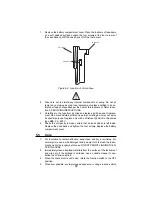
Page 18: ...ace the compartment cover If the Instrument still does not operate the internal fuse may be open For access to this fuse the case back must be removed WARNING To avoid electrical shock make certain th...

Page 19: ...ial purpose Replace only with a Littlefuse Type BLS or Bussman type BBS 2 A 600 V 4 Shake the unit gently to make certain that no loose debris is left inside Replace the case back and tighten the four...

Page 20: ...into a warm building Therefore do not attempt high voltage measurements until the Instrument has had time to dry completely 6 SERVICING INSTRUCTIONS An improperly repaired instrument may be dangerous...

Page 21: ...76 R23 Resistor 184 1 1 2 W 1 110271 R24 Resistor 2 02 k 1 1 2 W 1 110270 R25 Resistor 16 8 k 1 1 2 W 1 110292 R26 Resistor 1 21 1 2 Bobbin 10 675499 R27 Resistor 12 22 1 2 Bobbin 10 675201 R28 Resist...

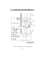
Page 22: ...22 Figure 6 1 Schematic Diagram 14510 2 Volt Ohm Milliammeter 6 2 Schematic Diagram 14510 2Volt Ohm Milliammeter...

Page 23: ...23 NOTES...

Page 24: ...24 SIMPSON ELECTRIC COMPANY 853 Dundee Avenue Elgin IL 60120 3090 847 697 2260 FAX 847 697 2272 Printed in U S A Part No 06 114022 Edition 3 11 02 Visit us on the web at www simpsonelectric com...

Reviews: