17
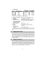
tion; the result is the resistance value in ohms. (“K” on the dial and panel
stands for “one thousand.”)
NOTE: The resistance of nonlinear components will measure differently from
one resistance range to another. For example: a diode could measure 80
ohms on the RX1 range and 300 ohms on the RX10 range. The difference in
the reading is a result of the non-linear diode characteristic and does not
indicate faulty operation of the ohmmeter circuit.
8.
Disconnect ends of test leads and return the range switch to the OFF
position after resistance measurements are completed.
5.
OPERATOR MAINTENANCE
This section describes those functions necessary to maintain the Instrument
in an operating condition and which may be performed by the operator or
user. This Instrument is carefully designed and constructed with high quality
components. By providing reasonable care and following instructions in this
manual, the user can expect a long, useful service life of the Instrument.
Servicing, other than that which is described in this Section, should be per-
formed only by qualified personnel, by one of the Authorized Service Centers
or by the factory.
5.1
Inspection
The user is protected from electrical shock by the insulation of the Instrument
and the test leads. Frequent examination of each should be made for any
insulation damage, such as cracks, cuts, chips, burns or deterioration that
expose internal metal parts or conductors, or any reduction in spacing be-
tween such metal and hand contact by the user. Replacement leads should
be the same as those originally supplied with the Instrument and can be ob-
tained from one of the Authorized Service Centers or the factory.
To avoid electrical shock, disconnect test leads from live circuits and from the
Instrument before opening the battery compartment cover.
5.2
Battery And Fuse Access
The batteries and 1/2-ampere fuse are located inside an isolated compart-
ment at the top-rear of the Instrument case. To open the compartment, pro-
ceed as follows:
Place the Instrument face down on a soft padded surface and unscrew the
single captivated screw on the compartment cover. Remove the cover from
the case and set it aside. Batteries and fuse now can be replaced.
NOTE: If replacement of the 2-amp high current interrupting fuse is neces-
sary, the Instrument case must also be removed (see paragraph 5.5 and Fig-
ure 5-2).
!
Summary of Contents for 14510-2
Page 1: ...Simpson 14510 2 Volt Ohm Milliammeter OPERATOR S MANUAL...
Page 4: ...4 NOTES...
Page 5: ...5 NOTES...
Page 23: ...23 NOTES...

