20 | Operation
26
24
22
20
18
16
14
12
10
8
6
4
2
0
LO
re
spo
nse
pa
ram
ete
rs
HI
res
po
nse
pa
ram
ete
rs
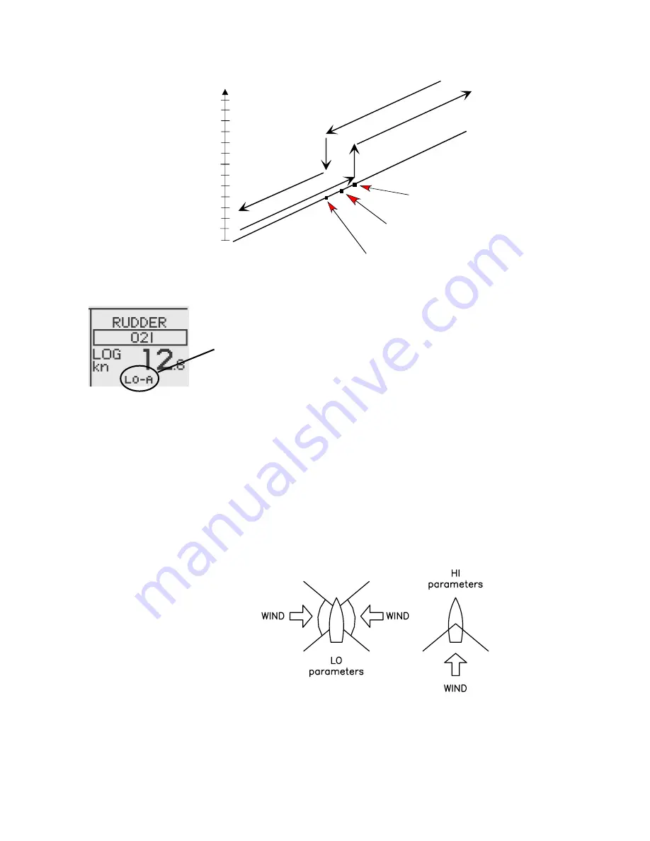
Transition Speed set to 9 Knots
Transition to LO parameters
with increasing speed: 10 Knots
Transition to HI parameters
with decreasing speed: 8 Knots
Speed
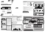
Display legend
HI-A
High response parameters set automatically
LO-A Low response parameters set automatically
HI-M High response parameters set manually
LO-M Low response parameter set manually
Power boats
On power boats the automatic selection of HI or LO is
determined solely by the speed of the boat as shown in
the diagram above.
Sailboats
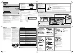
When sailing in WIND mode, the parameter set is
determined by the speed of the boat and the direction of
the wind as per below.
So if you loose too much speed e.g. when tacking, the
parameters will change to HI to gain sufficient rudder
response. This should be observed when setting the
transition speed on sailboats. See also Wind response
on page 22.
Summary of Contents for AP28
Page 1: ...OPERATOR MANUAL AP28 AUTOPILOT 20222527 A Sw 1 1 English A P 2 8 ...
Page 6: ...6 AP28 Manual Blank page ...
Page 45: ...Operation 45 Blank page ...
Page 50: ...50 Operation Blank page ...
Page 68: ...68 Main menu Blank page ...
Page 101: ...Setup at installation 101 DISPLAY 1 DAMPING 1 LANGUAGE NONE FLYBRIDGE COCKPIT DISPLAY 2 ...
Page 104: ...104 Setup at installation Blank page ...
Page 108: ...108 IS20 Alarm system Blank page ...
Page 120: ...120 Optional equipment Blank page ...
Page 124: ...Glossary 124 Blank page ...


