background image

EQ33 Installation and service 

Chapter 9-7

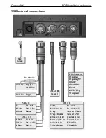
9.5.1 Power supply connections

The internal voltage regulator will allow the EQ33 to operate normally within 
the power supply voltage range from 10 to 32 V DC. The EQ33 is connected to 
external power (battery) by means of the supplied power/NMEA cable. Cable 
length is approximately 2 meters.
After connecting the cable to the power source, push the plug as far as it will 
go into the nine pin receptacle marked “PWR” on the rear of the cabinet and 
turn the plug’s coupling ring clockwise until it makes a click.

9.5.2 Fuse

Warning! A fuse should always be installed to protect the unit.
Using a fuse which is not specified for your equipment can cause it to blow 
the instant the EQ33 is switched on or it will not protect the equipment as 
intended – see fuse rating in section 9.10 Specifications.

9.5.3 Transducer connection

Most transducers are supplied with a 10 meter cable for connection to the 
echosounder unit – EQ33. Push the female plug, as far as it goes, into the 
receptacle marked “ECHO” on the rear of the cabinet and turn the plug’s cou-
pling ring clockwise until it clicks into locked position 

 The EQ33 must be turned off while connecting/disconnecting the trans-

ducer cables.

Recommended transducers

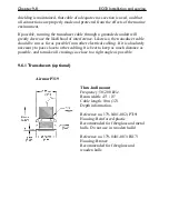
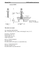
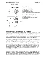
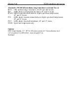
Airmar single element two-frequency 50/200 kHz transducers i.e. B744, P319, 
B45, B256, P66 and P52.

9.5.4 NMEA0183 interface connection

NMEA0183 interface connection is made via the combined power and NMEA 
cable.

9.6 Basic transducer and cable information

The installation should be carefully planned in advance, keeping in mind the 
standard cable length of 10 meters (32 feet) which is connected to the trans-
ducer. In the event where the standard cable is not long enough, up to an addi-
tional 10 meters (32  feet) may be connected without a noticeable reduction of 
the performance. The cable must be of the same type as the standard cable.

 The EQ33 must be turned off while connecting/disconnecting the trans-

ducer cable.

The use of longer cable runs, while possible, always increases the likelihood of 
increased interference and decreased performance. Care must be taken when 
increasing the cable lengths to ensure that proper, adequate and consistent 

Summary of Contents for EQ33

Page 1: ...M A N U A L Simrad EQ33 Echosounder 183 2300 702 02121 10...

Page 2: ......

Page 3: ...er 3 Position menu 3 Position menu 3 1 3 1 Position display 3 1 Chapter 4 Pilot menu 4 Pilot menu 4 1 4 1 Highway display 4 1 4 2 Navigation setup 4 1 Chapter 5 Echosounder operation 5 Echosounder ope...

Page 4: ...1 Installation notes 9 1 9 2 Installation of EQ33 Echosounder 9 3 9 3 Location for display unit 9 4 9 4 Installation of DS33 Dual Station 9 5 9 4 1 Operation of DS33 Dual Station 9 5 9 5 Electrical c...

Page 5: ...ith the key functions menu structure and rotation of pages screens described in chapter 2 before you start out and then proceed with section 2 5 Initial start up For quick location of a certain term p...

Page 6: ...round using the ground screw at the rear of the unit Good grounding should also be exercised for any equipment connected to the EQ33 Quality service personnel The EQ33 is sealed and does not contain a...

Page 7: ...le between 50 and 200 kHz echo displays B LCK Press B LCK from any other display will call up the bottom lock display Press B LCK again will toggle A scope on off Press B LCK for 2 seconds will toggle...

Page 8: ...range by the numeric keys 1 9 or adjust with the keys Key 0 will select Auto Range Bottom expansion Press B LCK from any display see section 1 3 1 or with echo display in active screen the function ca...

Page 9: ...y and page system The EQ33 Echosounder has a multi function screen and data presen tation system with full screen or a split screen with echo display and data Full screen Split screen There are four p...

Page 10: ...s this interval can be changed refer to section 7 1 Press PAGE again to return to normal opera tion Example of how to change a pre set page For instance if you wish to have the Echo 50kHz display inse...

Page 11: ...cope on off Hold two seconds to toggle between 50 and 200 kHz frequency B LCK Shortcut to Bottom lock display from any other display Bottom lock is a combination of standard echo display and extended...

Page 12: ...e menu bar across the screen some of the menus have been abbreviated However the last selected menu will be high lighted and if it s an abbreviation of the menu then the complete menu title is written...

Page 13: ...Most functions in the menus are general and can be called forward at any time but a few are related to a certain menu s and can only be called forward or activated in the appropriate menu Inactive fun...

Page 14: ...ut to start out it will be wise to select the display language you prefer to use MENU Call up the menu bar and 5 1 press 5 1 to call up the language display Press up on the cursor to jump to the botto...

Page 15: ...d Position display Trip log 1 and 2 Position in three deci mals in minutes Water speed speed over ground Course magnetic or true Editing of position display Reset log or change the start figure adjust...

Page 16: ...Chapter 3 2 EQ33 Position menu CLR Press CLR to reset log Toggle between available values change time and date ENT Confirm entry...

Page 17: ...uld be Cursor Waypoint Route or Track navigation see next page 4 2 Navigation setup MENU Call up the menu bar and 2 1 load Highway display Since there is no navigation mode active you will receive the...

Page 18: ...track error S Speed over ground B Bearing to approaching WP D Distance to waypoint V Speed towards WP velocity Bottom line indicates name number of approaching waypoint or routepoint Ship s position a...

Page 19: ...y the transmitter is converted into an ultra sonic signal by the transducer and transmitted into the water Any reflected signals from intervening objects such as a fish school are received by the tran...

Page 20: ...lay can be set up sepa rately The low frequency display will show deep water bottom contours and the high frequency display will show the mid water section with trawl targets or bait fish in a higher...

Page 21: ...t to AUTO transmission pulse length A SHORT set to AUTO water temperature T in Celcius or Fahrenheit in 1 10 degrees water or SOG speed S in knots or kilometers hour or miles hour units can be changed...

Page 22: ...om area can be magnified for better separation of echoes The actual size of the expansion window can be adjusted in the Setup display for 50kHz 200kHz As an example from active Echo 50kHz display MENU...

Page 23: ...Hz As an example from active Echo 50kHz display MENU Call up the menu bar and 3 4 activate VRM expansion or just press ZOOM Call up the zoom display The zoom level can be selected in seven steps rangi...

Page 24: ...mple from active Echo 50kHz display MENU Call up the menu bar and 3 5 turn A scope ON or toggle the A scope function on off from active echo display STND press either STND from standard echo display o...

Page 25: ...d Move the VRM up down Adjust the range by means of the keys CLR Turn VRM off again 5 7 Depth temperature diagram MENU Call up the menu bar and 3 6 activate Depth temperature diagram Present water tem...

Page 26: ...ng from 0 10m to 0 3000m Toggle between values with keys Color for depth and temperature can be changed Toggle between available colors by means of the keys Scale for temperature can be set to 0 10 0...

Page 27: ...ransmitting at 50 and 200 kHz MENU Call up the menu bar and 3 7 activate Echosounder setup display Use the cursor key to move cursor around in the display Select new values by means of the keys ENT Co...

Page 28: ...rs in warm waters and decreasing in cold waters Time distance scale will indicate the elapsed time or distance for the echo picture The readout will appear in the upper part of the echo display Toggle...

Page 29: ...ge AUTO Gain 30dB White line OFF Expansion window 6 m TVG Normal 20 log R Ping to ping filter ON Signal threshold OFF Color threshold OFF Depth grid OFF Transmit pulse length AUTO Transmit power AUTO...

Page 30: ...Chapter 5 12 EQ33 Echosounder operation...

Page 31: ...wind data from connected instruments Wind data the wind instrument can provide both wind direction and wind speed and the readings can be shown in relative or true when the data is supplied from conne...

Page 32: ...h to change Toggle between settings or 0 9 Key in new figure ENT Confirm entry and return to Wind display Damping level can be set to LOW MEDIUM or HIGH The higher level the more steady and slow react...

Page 33: ...Message from VHF will require that the EQ33 is connected to a compatible Simrad VHF radiotelephone The message from the VHF will appear in a pop up window together with an acoustic alarm Press CLR to...

Page 34: ...Chapter 6 4 EQ33 Miscellaneous menu...

Page 35: ...1 load Speed alarm units language display Setup for speed LOG speed sensor ON LOG speed calibration 019000 PULSES nm Speed alarm maximum SOG 000 0kn OFF Speed alarm minimum SOG 000 0kn OFF To select...

Page 36: ...d sensor set to ON the position display will show water speed from external log sensor via ECHO port with NMEA sentence VHW set to ON the readout will show water speed from external water speed instru...

Page 37: ...n is installed in the unit Serial number indicates the unit s serial number Interface software version indicates which version is installed in the unit for technicians only PAGE rotation interval can...

Page 38: ...available in the setups MENU Call up the menu bar and 5 2 load NMEA interface PAGE Toggle between the two pages of sentences refer to 7 2 1 default settings and 7 2 2 description of sentences Toggle...

Page 39: ...a Heading HDG ON Position data Position GLL ON Course VTG ON Speed VTG ON Navigation data Navigation APB RMB XTE ON Interface setup OUTPUT Port NMEA0183 Sentence String Status Water data Depth below k...

Page 40: ...GPS data GGA Global Positioning System fix data VTG Track made good course and ground speed Description of NMEA0183 navigation input sentences APB Autopilot sentence B RMB Recommended minimum navigat...

Page 41: ...y for Alarm output Interface setup alarm Output pin 1 2 ON Alarm stand by level LOW MENU Exit Accept ENT The stand by level can either be LOW 0 volt or HIGH 5 volt Use cursor to move around in display...

Page 42: ...7B 04 Holland 2E 28 Calcutta 8B 05 British 3B 29 Bangladesh 6C 06 Lofoten Norway 3E 30 Hokkaido 9C 07 German 3F 31 Tohoku 6C 08 N Baltic 4B 32 Kyusyu 7C 09 NW Spanish 4C 33 Namaqua 4A 10 Trondelag N 4...

Page 43: ...e delay If required go to Offset and key in a positive or negative offset 0 9 Key in a positive or negative offset to the time delay toggle positive negative with ENT Confirm entry List of Loran C cha...

Page 44: ...re not adjustable Palette 5 to 9 can be customized to suit individual needs and wishes If you wish to make your own special palette setup in e g palette 5 then 5 Select Palette setup 5 Use cursor to s...

Page 45: ...pace Press the CLR key to delete everything from cursor position and to the right of cursor in that row 7 7 Factory settings DELETE MEMORY It will be possible to erase all sounder set tings or NMEA se...

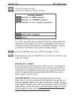
Page 46: ...o exit function without having made any changes POWER OFF RESET In case for some reason the unit is totally locked i e no immediate response from the keypad then first try to reset the unit by discon...

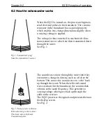
Page 47: ...vate the transmitter The transmitter sends a high voltage transmit ping to the transducer mounted on the hull At that point the trans mitter s job is done and the receiver takes over see fig 1 in sect...

Page 48: ...e water See Fig 1 Fig 1 Transmitted ping from the transmitter receiver The sound waves move through the water until they encounter a change in density such as a fish or the bottom This causes the soun...

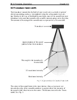
Page 49: ...amount going out to the sides The amount of focusing of the sound beam is expressed as a beam width Transducer Approximation of the sound pattern below the transducer This angle is the transducer s be...

Page 50: ...sh When the vessel is at rest the echo traces will appear stretched and flattened As the vessel s speed becomes greater the echo traces will become shorter and more arched The reason for this change i...

Page 51: ...er of reasons all user related decisions setups etc should be noted in these two pages as they occur This information may be helpful if your unit has been updated with new software reset or in for ser...

Page 52: ...Chapter 9 2 EQ33 Installation and service Other important settings continued...

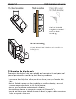
Page 53: ...168 mm 6 6 EQ33 Installation and service Chapter 9 3 9 2 Installation of EQ33 Echosounder The EQ33 can be flat or bracket mounted overhead bulkhead or console Bulkhead mounting approx 10 tilt allowing...

Page 54: ...ble and convenient for navigation and general operation after considering the following conditions you can see the ship s bow when you raise or lower your eyes from the dis play there is limited expos...

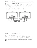
Page 55: ...cal in size so the same installation guides can be applied when perform ing the installation Refer to section 9 5 for details on pin numbers EQ33 DS33 9 4 1 Operation of DS33 Dual Station The main uni...

Page 56: ...4 Orange white dot Dual station 1 to 1 5 Orange yellow dot Dual station 2 to 2 6 Blue white dot PC Link TxD 7 Blue yellow dot PC Link RxD Ship s Ground 1 2 Red Supply 10 32 Volts 3 4 Black Supply NME...

Page 57: ...goes into the receptacle marked ECHO on the rear of the cabinet and turn the plug s cou pling ring clockwise until it clicks into locked position The EQ33 must be turned off while connecting disconnec...

Page 58: ...un as far as possible from other electrical cabling If it is absolutely necessary to pass close to other cabling it is best to keep as much distance as possible and to make all crossings as close to a...

Page 59: ...er 9 9 Airmar P52 Transom mount Frequency 50 200 kHz Beam width 45 15 Cable length 10m 32 Speed temperature depth information Reference no 179 0401 001 Housing Chemical resistant high impact plastic a...

Page 60: ...dates hull thickness Min no fairing 6 mm 1 4 Max with fairing 83 mm 3 1 4 Frequency 50 200 kHz Beam width 45 15 Cable length 10m 32 Depth information Ref no 179 0401 004 B45 Housing Bronze Recommended...

Page 61: ...l s movement through the water will seriously degrade the transducer s performance Therefore the transducer should be located well clear of any water intake or discharge line and also clear of any pro...

Page 62: ...interference from propel ler noise can be a significant problem This can be seen as an increase in the noise on the echosounder display when the propeller speed is increased To help reduce this the tr...

Page 63: ...tions are tight and that no cables are frayed or worn Transducer periodically clean the face of the transducer with a plastic uten sil using a scrubbing action Do not use a harsh abrasive or a solvent...

Page 64: ...ure appears normal but no target are shown or only random noise is seen Check that the correct transducer frequency is selected Go to Echosounder setup and select transducer frequency Check that the t...

Page 65: ...0183 1 port NMEA 2000 optional Alarm signal output 5 V 50 mA Fuse 4 0A slow Echosounder section Frequencies 50 or 200 kHz selectable Transmit power 600 watt RMS 4 800 W PP Impedance 175 425 ohms Displ...

Page 66: ...cer 45 and 15 beam B744V 600W bronze thru hull triducer depth speed and temperature 45 and 15 beam P52 600W plastic transom mount triducer depth speed and temperature 45 and 15 beam P319 600W plastic...

Page 67: ...w you to adapt the system more specifically to your needs You may set Units of measure feet fathoms meters etc Menu languages Scroll speed etc Depths DK Depth below keel DS Depth below surface DT Dept...

Page 68: ...ers kh kilometer per hour mi statute mile 1 mile is 1 609 meters mh mile per hour MENU the selection of main menus will be shown in the upper part of the screen Leaf through the menus by means of the...

Page 69: ...in ning at say 200 meters and going to 300 meters depth Scroll speed is the rate of movement of the targets on the display screen moving from right to left It is adjustable to allow the user to show a...

Page 70: ...r net sounders In OFF position the TVG is inac tive which means that the sounder operates with a fixed gain between each transmitter pulse Auto range is switched to manual White line is a control whic...

Page 71: ...ation setup 5 11 range 5 3 5 11 A 3 Echosounder features continued return to sounder presets 7 12 sampling 5 9 scroll speed 5 11 A 3 scroll synchronization 5 11 A 3 selecting displays 5 1 5 2 setup 5...

Page 72: ...aster reset 7 12 Measurement units A 2 setup 7 1 Menu bar 2 4 Menu layout 2 5 Miscellaneous menu 6 1 Navigation setup 4 1 Night display 7 10 NMEA interface 7 4 return to NMEA presets 7 12 Page system...

Page 73: ...eclaration of Conformity The EMC Directive Article 10 1 Undersigned are herewith declaring that Product SIMRAD EQ33 Echosounder is in accordance with the protection requirements in the EMC Directive 8...

Page 74: ......
Page 75: ...s claimed to be defective ON BOARD SERVICE can be arranged by authorized local service dealers or national distributors upon request Labor costs for the repair replacement of the defective modules par...

Page 76: ..._____ EQUIPMENT ________________________________________________________________________ ____________________________________ ____________________________________ ______________________ ______________...

Page 77: ...______________________ ___________________________________________ TYPE __________________________________________________________ EQUIPMENT ___________________________________________________________...

Page 78: ...__________________________________ _________________________________________________________________________ _________________________________________________________________________ _________________...

Reviews: