| 19
Installation |
Loop M User Manual
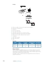
Control two devices with one bypass switch
1D 1C 1B 1A
1E
1G 1H
4D 4C 4B 4A
4E 4F 4G 4H
1D 1C 1B 1A
1E
1G 1H
4D 4C 4B 4A
4E 4F 4G 4H
A
B
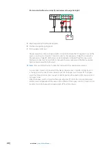
The example shows two loads (light bulbs) connected between the DC negative bus and the
green connector pin 4A and 4F. Connector pin 4A is the output pin of relay R1 and pin 4F is
the output pin of relay R2. Both relays can be individually controlled from the Loop system.
An external bypass switch is connected to the black connector pin 1C and 1B. Connector pin
1C is the bypass pin for relay R1 and connector pin 1B is the bypass pin for relay R2.
While the bypass switch is closed, the relays will be closed independent of the status in the
software. If the bypass switch is closed, it is not possible to turn any of the lights off from the
software.
Example A: Two diodes are connected to avoid conflicts between the outputs when
controlled from the software.
Example B: A two pole switch is used to avoid conflicts between the outputs when controlled
from the software.
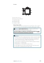
Connecting an indicator light to a relay output
1D 1C 1B 1A
1E
1G 1H
2C 2B 2A
2E
2G 2H
1D 1C 1B 1A
1E
1G 1H
2C 2B 2A
2E
2G 2H
The example shows a load (light bulb) connected between the DC negative bus and the
gray connector pin 2E. Connector pin 2E is the output pin of relay R8 and can be controlled
from the Loop system. In addition to the main load an indicator light is connected between
connector pin 2E and the DC negative bus.
An external bypass switch is connected to the black connector pin 1H. Connector pin 1H
is the bypass pin for relay R8. While the bypass switch is closed, the relay will be closed
independent of the status in the software. If the bypass switch is closed, it is not possible to
turn the light off from the software.
The bypass switch is optional and only necessary if you want to be able to bypass the relay/
software.
Example A: The indicator light is connected directly to the relay output pin. For safety, the wire
size must be of the same dimension as the main load wire.
Example B: The indicator light is connected via a fuse to the relay output pin. The fuse rating
and wire dimension should be selected based on the indicator light’s specification. The fuse
should be connected as close to the relay output as possible.


